Understanding the USB 3.1 protocol
A look at USB 3.1, which offers data rates of up to 10Gbit/s, and the way that the USB 3.1 protocol has changed to support this rate.
The USB standard keeps evolving, with the recent USB 3.1 release offering data rates twice those of USB 3.0. The new spec is backwards-compatible with previous specs, and is expected to work with existing software stacks.
In practice, this means the USB 3.1 protocol offers enough bandwidth to carry full 1080p/60 HDTV signals, or to transfer data to storage devices at up to 450Mbyte/s.
Some terminology
As USB has developed, so has its terminology. Here’s a summary:
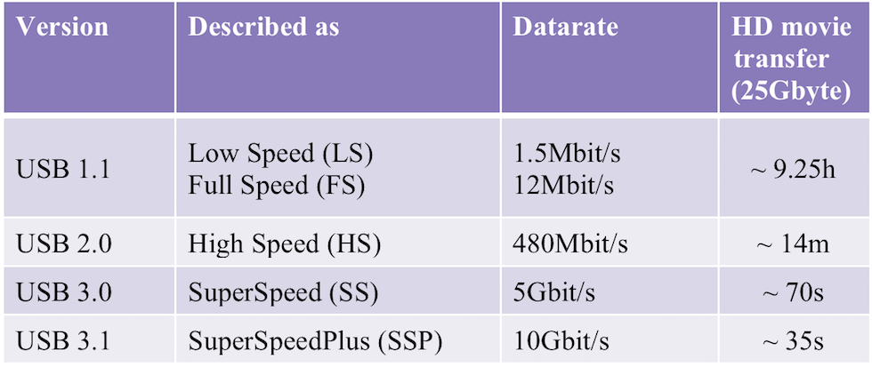
Table 1 The evolution of USB terminology (Source: Synopsys)
Other terms used include:
- Generation 1 – operating at 5Gbit/s
- Generation 2 – operating at 10Gbit/s
- SuperSpeed – bus, system, etc. that supports Gen 1
- SuperSpeedPlus – bus, system, etc. that supports greater than Gen 1 speeds
- Enhanced SuperSpeed – Gen 1 and above speeds
What’s new in USB 3.1
There are changes in every layer of USB 3.1.
Physical layer
Cables and connectors have been improved to cope with the 10Gbit/s data rates of USB 3.1. Although USB 3.1 will run over standard A and micro B type connectors, a type C connector has been introduced that can be used at both ends of a cable, and can be flipped over. The Type C connector is smaller and thinner than previous connectors, has 24 pins (more than twice as many pins as the previous connectors, to enable flipping), and runs at a slightly higher bus voltage of 5.5V, rather than 5.25V.
The higher-frequency operation of USB 3.1 means that designers may have to use repeaters to counter cable losses.
These repeaters must meet the transmitter and receiver specifications applied to a host or a device. They have to implement elastic buffers, skip insertion and removal, and support link power management commands, low-frequency periodic signalling (LFPS), and a new speed negotiation protocol in USB 3.1. They also have to be backward compatible with the Generation 1 link training and status state machine (LTSSM).
Link layer
The USB 3.1 link layer definition tries to preserve a lot of the USB 3.0 link layer architecture. There are extensions in link flow control, but there’s a similar packet framing and LTSSM structure. The goal is to offer error performance as good as, or better than, that of USB 3.0.
USB 3.1 addresses an issue with the USB 3.0 protocol, in which a single-bit error can cause the link to go into recovery in two cases: with SKP ordered sets; or with start link commands. This can cause error rates of up to 5.7×10⁻¹⁵.
USB 3.1 uses a new encoding scheme, known as 128b/132b, rather than the 8b/10b encoding used in 3.0, which cuts the encoding overhead from 20% to 3%. The 4bit header in the 128b/132b scheme indicates whether the block represents control or data. The header is encoded in such a way that a single-bit error can be self-corrected, and a two-bit error can be detected so the protocol can enter a recovery process.
USB 3.1 packet structure
The USB 3.1 packet structure begins with the data packet header, which can be encoded to represent a deferred or non-deferred packet. The data packet header has two copies of the length field, to increase the robustness with which framing symbols are detected within the 128b/132b encoding scheme, given a single-bit error.
Traffic classes
USB 3.1 has two classes of traffic, compared to one in USB 3.0.
Type one traffic refers to transaction packets, link-management packets, isochronous timestamp packets, periodic data packets and deferred data packet headers. Type two traffic refers to asynchronous data packets.
This classification enables type-one traffic to be given priority over type-two traffic. In turn, this means USB 3.1 can do a better job of ensuring that periodic transactions can meet their bandwidth requirements.
Buffer credits defined in USB 3.0 as covering the data packet headers now cover the data packet header and its payload, replacing the header buffer credit used in USB 3.0. This helps with payload flow control.
Start-up speed negotiation protocol
USB 3.1 adds a new start-up speed negotiation protocol, designed to get the link up to the highest rate supported by both devices. It uses the LFPS handshake introduced in USB 3.0, adapting it slightly to turn it into a pulsewidth modulation message called LBPM (for LFPS-based PWM message).
The transmitter drives its LFPS for about a quarter of a period to declare a logic One, and for about three quarters of a period to declare a logic Zero. This means that the transmitter and receiver can communicate before the link has been trained to a particular data rate.
The LTSSM is updated in USB 3.1 with new states that support this protocol.
In summary, USB 3.1’s link layer gets a new encoding scheme with a much lower encoding overhead. Its data rate has doubled, and the probability of entering a recovery process due to a single-bit error has gone to zero. The probability of entering a recovery process due to a single- or a multi-bit error has also been cut, from 5.7×10⁻¹⁵ to 1.8 x10⁻²².
Protocol layer
The most important change to the protocol layer in USB 3.1 is the addition of support for Multiple INs, which allows hubs to maximize throughput, and ordering rules for these Multiple INs. The precision time management scheme introduced in USB 3.0 has been updated with a new field for the transfer type and packet headers. The route string has been enhanced to include a weight for the device to host data packets. And there is more bandwidth for isochronous transactions.
Multiple INs
Multiple INs play an important role in ensuring that the enhanced bandwidth of USB 3.1 can be exploited.
Imagine a 10Gbit/s USB 3.1 host connected to a 10Gbit/s USB 3.1 hub, which is connected to a 5Gbit/s USB 3.0 device, and a 10Gbit/s USB 3.1 device. Without Multiple INs, a lot of bandwidth is wasted while the 5Gbit/s device is transmitting upstream.
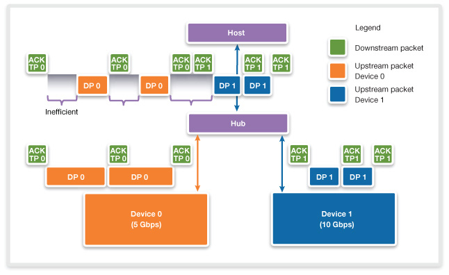
Figure 1 Without Multiple INs, USB 3.1 bandwidth can be wasted (Source: Synopsys)
With Multiple INs, the USB 3.1 host sends an IN request to both devices and the hub buffers the data coming from the 5Gbit/s USB 3.0 device and transmits it whenever there’s capacity on the upstream port, maximising the use of the available bandwidth.
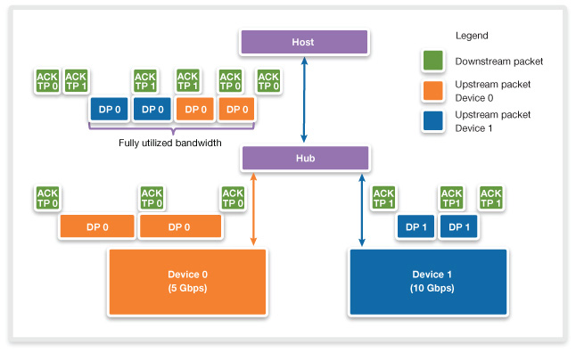
Figure 2 With Multiple INs, USB 3.1 bandwidth can be efficiently used, although hubs need to do more buffering (Source: Synopsys)
This means, of course, that hubs need more buffering capability. USB 3.1 hubs use store-and-forward strategies, instead of a repeater/forwarder architecture as used in USB 3.0.
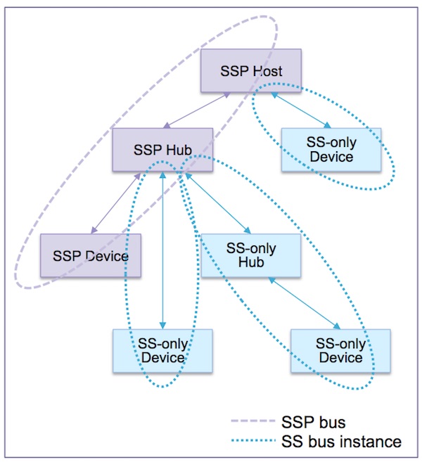
Figure 3 Mixing USB 3.1 and 3.0 hosts, hubs and devices leads to the creation of different forms of bus instances (Source: Synopsys)
In the diagram (above), multiple USB 3.1 hubs and USB 3.0 hubs are connected to a USB 3.1 host. This host can schedule Multiple INs to the USB 3.1 devices. It can also schedule Multiple INs to different USB 3.0 endpoints, as long as they are on different bus instances. A bus instance starts whenever there’s a transition between USB 3.1 and USB 3.0. However, the host cannot use Multiple INs when scheduling to USB 3.0 endpoints connected to a USB 3.0 hub.
Another addition to the protocol layer is transaction packet labeling, which identifies a packet as control, isochronous, interrupt or bulk.
USB 3.1 hubs
The introduction of Multiple INs, extra buffering, and store-and-forward protocols helps USB 3.1 hubs make the most of upstream bandwidth. Hubs can now prioritize periodic over asynchronous packets, perform round-robin arbitration within data packets, and prioritize transaction packets over data packets.
Packet forwarding
Packet forwarding in USB 3.1 is designed to allow fair arbitration between devices, even if they exist in a lower layer of the connection topology.
The round-robin arbitration mechanism that controls access to the host, irrespective of where devices exist in that topology, uses weightings.
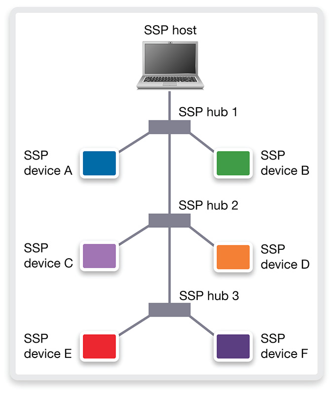
Figure 4 USB 3.1 arbitration mechanisms use weightings to ensure fair use of the available bandwidth (Source: Synopsys)
Each packet is given an initial weighting, depending on its speed, so Gen 1 packets get a weighting of 4, while Gen 2 packets gets a weighting of 8. The weight of the packet from a hub is the sum of all the weights of all the active downstream devices on it. Ports with heavier weights get proportionally more turns in the arbitration algorithm. In this way, devices at the lowest layer of a connection topology get fair access to bandwidth on the host.
Transaction packet labeling
The transaction packet labeling introduced in USB 3.1 needs some help from USB 3.1 hubs, which have to remember whenever there’s a transfer going downstream to a USB 3.0 device or hub. When that packet comes back upstream, it needs to attach a transfer-type label so that the rest of the hierarchy knows the type of transfer that applies to the packet.
Increased buffer requirements
As discussed, USB 3.1 hubs need extra buffering to manage their connections to slower USB 3.0 devices.
Consider a USB 3.1 hub using Multiple INs to accept upstream packets at the same time from a Gen 1 device on one port, and a Gen 2 device on another port. Because the Gen 1 device is sending its data at half the rate of the Gen 2 device, its packets are sent to the upstream host as every third packet in the upstream link. This means the hub has to buffer an extra packet from the USB 3.1 device.
In general, for the upstream flow per downstream-facing port, the USB 3.1 hub needs an extra 16Kbyte of buffer for asynchronous packets, an extra 16Kbyte of buffer for periodic packets, and storage for 32 data packet headers, 16 each for asynchronous and periodic packet types.
For the downstream flow each USB 3.1 hub also needs 18Kbyte of buffer for asynchronous packets, 18Kbyte for periodic packets, and storage for 18 header buffers, 18 each for asynchronous and periodic packet types.
Conclusion
The shift to USB 3.1 from USB 3.0 brings a number of important changes:
- doubling of bandwidth to 10Gbit/s
- coexistence of different data rates on the same wires
- more sophisticated link-speed negotiation
- separate handling of asynchronous and periodic traffic at all layers
- more efficient and robust 128b/132b encoding
- support for Multiple INs
- greater demands on hubs to do arbitration and extra buffering
- continuing backward compatibility with USB 3.0 and earlier protocols
- continuing software compatibility
More info
Synopsys readies USB 3.1 IP and verification support
Find out more about USB 3.1 and Synopsys’ implementation in its USB University USB 3.1 protocol overview video.
There’s also a related white paper, here.
Find out about USB 3.0, which USB 3.1 builds upon, in this series of articles:
USB 3.0 Protocol Layer – Part 1
USB 3.0 Protocol Layer – Part 2
Author
Eric Huang worked on USB at the beginning in 1995 with the world’s first BIOS that supported USB keyboards and mice while at Award Software. After a departure into embedded systems software for real-time operating systems, Huang returned to USB cores and software at inSilicon, which was acquired by Synopsys in 2002. Huang also served as chairman of the USB On-The-Go Working Group for the USB Implementers Forum from 2004-2006.