Managing power intent, signal isolation and level shifting in a UPF-based multi-voltage IC design
Power intent, signal isolation and level shifting can all be controlled in a UPF-based multi-voltage IC design through careful coding.
A hierarchical design flow offers advantages over a flat approach in part because it enables the problem to be broken down into blocks that can be worked on in parallel. However, these advantages soon diminish if vital information is lost during the decomposition of the design into blocks, or ignored when the blocks are integrated at the top level.
For this reason, it is important to ensure that the UPF information that accompanies each block is preserved. It is also important that the information remains consistent between the block and the top level. For example, if a block that has a supply port at one volt, then it has been optimized to work at one volt. When the block is integrated into the top- level, its supply port will be connected to the top-level supply with the expectation that it will also be at one volt. If this is not true, then the block implementation at one volt is no longer appropriate.
To ensure this, Design Compiler offers the command
propagate_constraints -power_supply_data
that checks the UPF constraints of the top level and the block, and then propagates the block-level constraints up to the top-level UPF.
UPF propagation in IC Compiler
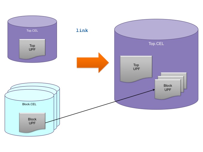
The same issue is addressed in IC Compiler using the link command, which implicitly executes Design Compiler’s
propagate_constraint -power_supply_data
command to integrate the block’s UPF constraints into the top-level UPF.
Figure 1 The link command ensures that UPF intent is carried forward during block integration (Source: Synopsys)
Other considerations
Domain merging
In a hierarchical block-based design, sub-blocks will be integrated into blocks that will in turn be merged into larger blocks until you reach the point of integrating very large blocks at the top level. The
propagate_constraints -power_supply_data
command helps ensure a consistent power management strategy by exposing a sub-block’s UPF constraints to the block into which it has been integrated. But once that has been done, the information about the sub-block’s power domain is redundant.
Design Compiler has a command
merge_domain
that merges the top-level power domain of a sub-block with the power domain into which it has been integrated.
Availability of supplies
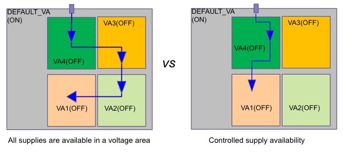
It’s important to control the availability of power supply nets in the physical implementation in order to implement the power intent efficiently. For example, if a design has multiple supply domains and all the different supply nets are available in all the domains, there is no constraint on how a net is routed to a domain in which it is actually used; it could pass through multiple domains unnecessarily. Making a tighter definition of the availability of power supplies should lead to a more efficient physical implementation.
Figure 2 Constraining the supplies to each domain can improve physical implementation (Source: Synopsys)
IEEE 1801, the UPF standard, specifies that supplies are available in all domains at the current scope and below. In order to provide better control of supply availability, Synopsys has implemented its own keywords, -domain and -extra_supplies.
For example, to control the availability of supply nets:
# Use -domain to control supply net availability
# And -reuse to extend the supply net availability
create_supply_net AO_VDD -domain PD_Top
create_supply_net AO_VDD -domain PDBlock -reuse
Or to control the availability of supply sets:
create_supply_set SSTop
create_supply_set SS_AO
# Available supplies in PDBlock are its primary supply and SS_AO
# SSTop is not available in domain PDBlock
create_power_domain PDBlock -supplies {extra_supplies_0 SS_AO}
Managing level shifter insertion
Hierarchical designs need level shifters to transition signals between blocks. Inserting these shifters must be done following a defined strategy because the availability of supply nets can cause confusion about where exactly you need to place the shifters.
For example, if a signal is transitioning between two power domains, the required level shifter could be placed in either of the power domains, or on the top-level net connecting them. Depending on your library cell availability and your design requirement, you might need to restrict where the level shifter can be placed – hence the need for an overall strategy.
This can be achieved with this code:
set_level_shifter PD1_LS -domain PD1 \
-applies_to outputs -location self
which states that all the outputs of Power Domain 1 need level shifters, and that they should be inserted within the Power Domain.
Managing source | sink
It’s important that any effort to manage the way in which signals are isolated is undertaken so that it works at both the block-level and when the block is in its top-level context.
For example, it would be possible to add isolation between a signal from internal logic running at one supply voltage and a block boundary, making that block’s behavior correct as a standalone entity. However, this overlooks the fact that the rest of the logic is running at a different voltage than the context in which it is to be integrated. In a block-based hierarchical design it is not possible to modify the circuitry within the block to correct this problem, creating an issue with properly isolating the block.
Managing isolation at the parent location
One way to avoid this problem is to decide that all isolation will be done outside the target block, in other words in each block’s parent block. With the UPF concept of Hiconn/Loconn, the same port can be defined as an input to the block, or as an output of the parent block. To insert isolation at the parent location, you can specify an isolation strategy for the target block with -location parent, which will enable insertion of isolation at the parent hierarchy. Or, specify the strategy at the parent hierarchy domain itself as -location self. In a hierarchical design flow, the block placement and routing process will be unable to place isolation cells in a parent context about which it has no information, so it is recommended to use the latter approach using -location self at the parent hierarchy domain.
Isolating heterogeneous nets
If a single net drives two or more blocks each having a different power domain to the driving block, it is not possible to selectively isolate the path to one of the driven blocks using
-source|-sink|diff_supply_only
on the output of the driving blocks. There are two ways around this: add a separate port on the driving block so that the signal can be separately isolated from each block; or change your UPF strategy so that isolation is done at the sink port of a signal.
Summary
Designers using a bottom-up, hierarchical design flow should start with RTL descriptions and UPF power intent files for each block of the design and for its top-level. Running the RTL and UPF for each block through Design Compiler will create a set of files that acts as an input for block-based place and route using IC Compiler, and for top-level synthesis. The final full-chip integration in Design Compiler uses the top-level RTL and UPF files, along with block abstracts derived either directly from the output of the block-level synthesis, or from the output of the block-level place and route process. The output of this synthesis is a full-chip netlist and UPF file, designed block-by-block from the bottom up taking into account each block’s power-management needs.
Supporting materials
This is the second article based on a Synopsys webinar entitled A Hierarchical, LowPower Design Approach for Gigascale Designs. The first article focuses on the impact of the way in which blocks are represented in a design on implementing power management schemes.
Guide to UPF
Guide to IEEE 1801-2013 (UPF 2.1)
Synopsys Subset Support for IEEE 1801 (Solvnet ID: 021264)
Design Vision GUI: Low Power Design Made Easy: Create, Visualize and Debug Your Power Intent
Author
Viswanath K Ramanathan is a product engineer for Power Compiler, specializing in low power design implementation. Ramanathan has over 10 years of experience working in ASIC design, including areas such as Library characterization, logic synthesis through RC extraction, signal integrity analysis and timing sign-off. Ramanathan has a MSEE degree from Arizona State University.

