Your next node: find lithography issues early with DTCO
Pattern-based design/technology co-optimization (DTCO) estimates lithographic difficulty during the early stages of a new process technology node.
When developing a new process node, finding potential lithographic distortions or failures (hotspots) is critical at all levels—from standard cells to large IP blocks and full chip layouts. Prior node design rules get you part-way there. Then, in the early stages of the design cycle, a new process flow does not require highly sophisticated lithography simulation models from the foundry, as it is based on the fundamentals of image processing techniques. However, at this early stage, designers need to identify lithographically challenging patterns so they can avoid them in layouts or pass them to the foundry for further process and OPC recipe development.
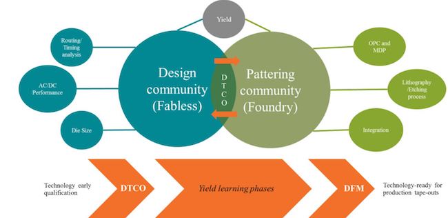
Standard design for manufacturing (DFM) techniques are designed for use on mature, production-ready technologies. Examples here include lithography-friendly design kits, lithography pattern-matching rules, manufacturing analysis and scoring (MAS) techniques, and yield enhancement automation. But for early technology definition, a pattern-based design/technology co-optimization (DTCO) flow that supports a bi-directional exchange of information between the foundry and the designers provides value to both sides. Figure 1 illustrates the difference between DTCO and DFM.
The DTCO flow begins with two basic elements: a design space explorer and a lithographic difficulty estimator. Together, they find the intersection between frequently used design styles and lithographically-challenging patterns to create a potential lithography hotspot pattern library. A pattern-matching tool can compare this potential library against incoming designs and standard cell libraries to generate a DTCO lithography pattern library. This then serves as the common platform that designers and foundry lithography patterning engineers use to explore and resolve litho pattern issues while going through different phases of yield learning cycles.
Design space explorer for lithography issues
The design space explorer finds all the possible useful patterns that can be used to identify potential lithographic problems or perform early testing for current rule decks. Yield ramp is accomplished for a new process by exposing a broad range of design layouts to a new manufacturing process. Foundries cannot do this with their internal IP alone, and are unlikely to have a broad set of customer data to play with at this stage.
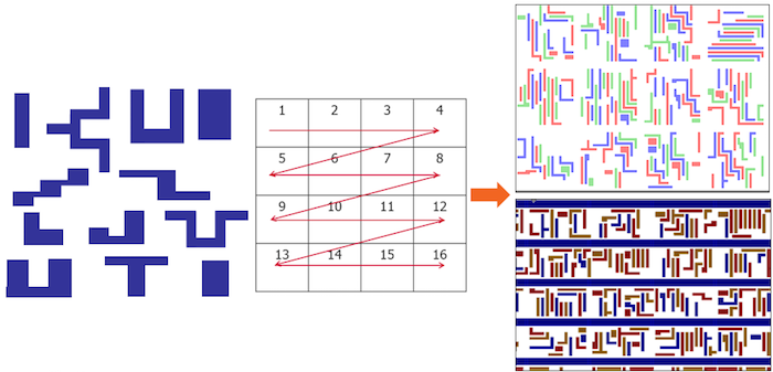
Instead, they can use a layout schema generator (LSG), a Monte Carlo based tool that generates ‘clips’ of arbitrary layout patterns that comply with the targeted design rules. Each clip is created by randomly placing unit patterns in a grid, where the random placement is guided by user-defined rules and weights. The LSG can generate layouts for both double- and triple-patterning applications, and standard cell-like layouts with pre-defined power rail templates, as shown in Figure 2. These patterns and layouts can provide enough accuracy and coverage for useful lithographic analysis and layout verification during early design starts.
Lithographic difficulty estimator
The goal of DTCO is to provide designers with early prediction of potential lithography problems before rigorous model-based DFM kits become available. A key component of this methodology, the litho difficulty estimator, leverages a couple of fundamental optical imaging concepts.
First, every pattern in the spatial domain can be represented in the frequency domain to determine the frequency content an image contains. These frequency terms are orthogonal, therefore, selecting any particular range of terms to reconstruct the image will do so to the greatest accuracy possible with those frequencies.
Second, the finite size of the entrance pupil of the optical scanner objective lens only captures a limited number of these spatial frequencies, also known as diffraction orders. This means that some high-frequency content of an image will be lost, degrading the quality of the reconstructed image. Therefore, an optical projection system could be abstractly considered as a low pass filter.
Detailed DTCO flow
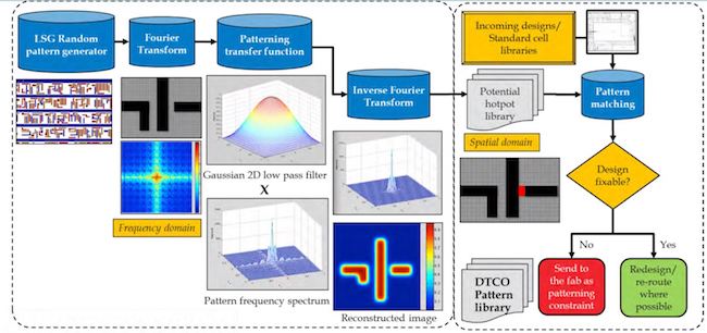
The litho pattern-based DTCO flow, also illustrated in Figure 3, consists of the following steps:
- The DTCO tool applies the Fourier Transform to the design space explorer output to convert the randomly generated DRC-clean layouts from spatial into frequency domain representation.
- A low-pass transfer function is applied to mimic the effects of the computational patterning process. The loss of the high-frequency component represents the introduction of image blurring effects that would highlight the regions of high risk from a printing standpoint. By reconstructing the image based on the selected low-frequency range, you can identify any weak spots due to the loss of high-frequency components.
- These patterns are stored in the potential hotspot pattern library.
The patterns are checked against real design data, such as full chips or standard cell libraries, using a pattern matching process. If matches are reported, designers can explore the option of fixing the layout geometry from the design standpoint. They can also share these real design matches with the foundry, for consideration as binding patterning constraints during OPC optimization.
Test cases
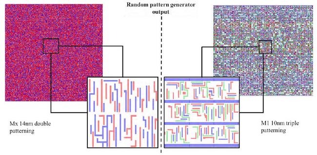
We validated the DTCO flow for Mx 14nm double patterning and M1 10nm triple patterning on two test cases using real design data. We started with the randomly-generated DRC-clean realistic designs, then tuned the 14nm Mx case to generate double-patterning-enabled layouts, and optimized the 10nm M1 case to generate triple-patterning standard cell-like layouts with a defined power-rail template.
Figure 4 shows the design space explorer output for both test cases.
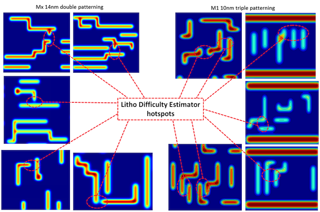
Next, we applied the frequency-domain computational patterning transfer function on each layout clip to introduce potential litho hotspot issues where the imaging fidelity is very sensitive to the loss of the high frequency component. These weak regions generate the library of potential litho hotspot patterns we discussed earlier. Figure 5 shows the output of the litho-difficulty estimator.
Once the potential lithography hotspots library was created, we tested it using a pattern-matching tool against real design data that included full chip designs and standard cell libraries. Since the two case studies were based on relatively mature technologies, we were able to verify that these hotspots were found on the real designs, and validated using rigorous lithographic simulation.
Of course, this verification step may be not possible for early technology definition cycles. In that case, the DTCO pattern library can be shared with litho and process engineers as patterning constraints to be considered during OPC optimization phases.
Summary
DTCO helps to rapidly determine patterning difficulty based on the fundamentals of optical image processing techniques. It can analyze the frequency content of design shapes to determine patterning difficulties using computational patterning transfer. With the help of a Monte-Carlo random pattern generator, the DTCO flow can identify a set of difficult patterns that can be used to evaluate the design manufacturability and help with the optimization phases of post-tape out flows.
The DTCO flow provides designers with early predictions of potential problems before the rigorous model-based DFM kits are developed and establishes a bi-directional platform for interaction between the design and the manufacturing communities.
If you would like to read a more in-depth discussion of the DTCO process, download a copy of the white paper, Estimating Lithographic Difficulty During Process Node Development with Calibre Design/Technology Co-Optimization.
About the authors
Wael ElManhawy is a Lead Technical Marketing Engineer supporting Calibre LFD tools and technologies in the Design to Silicon division of Mentor, a Siemens Business. He has 20 years of experience in the EDA and semiconductor industries. Wael received his MSc. from Cairo University. He may be reached at wael_manhawy AT mentor DOT com.
Joe Kwan is the Product Marketing Manager for Calibre LFD and Calibre DFM Services in the Design to Silicon division at Mentor, a Siemens Business. He previously worked at VLSI Technology, COMPASS Design Automation, and Virtual Silicon. Joe received a BA in Computer Science from the University of California, Berkeley, and an MS in Electrical Engineering from Stanford University. He can be reached at joe_kwan AT mentor DOT com.
