Cooling power electronics at room level
“The most viable method of airflow design prior to testing is with CFD simulation-based design software such as FloEFD. FloEFD allows E-Cooling to quickly build and assess the viability of an airflow and thermal design.”
Karim Segond, Consulting Engineer, E-Cooling.
Power electronics challenges
The conversion of electrical power using power electronics is a key technology that enables much innovation in electric vehicles as well as electricity production. Though the applications vary greatly, they have to balance two considerations: the electric components generate a significant amount of heat, but must be trusted to operate reliably. A key factor in the reliability of electronics is the operating temperature. To maintain that temperature within specifications with a high heat dissipation, a proper thermal design is required.
The market in inverter solutions for photovoltaics is growing, with the Middle East, Africa and India expected to become massive users. In these regions, an average summer’s day temperature of 50°C is common. The customers require reliable inverters that can be integrated within enclosures or containers without air conditioning. As the cooling air takes away the electrical losses, its temperature usually exceeds the environmental temperature. There is also a need to avoid dust or sand entering the electric enclosures. Therefore, filters are necessary, despite large pressure losses.
E-Cooling, an engineering consultancy based in Germany, is an expert in the thermal design for power electronics, transformers and chokes at the component level or at room level where the computational domain enhances a complete enclosure, container or room. At room level, its designs must ensure that the cooling path provides adequate airflow to all critical components.

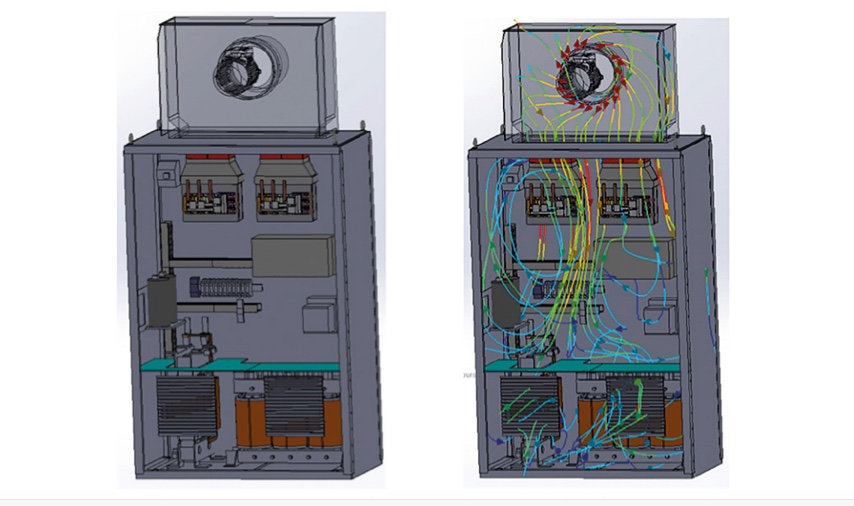
Figure 1. (Left) Enclosure with electric components and fan and (right) streamlines from the fan colored with velocity (Mentor/E-Cooling)
Cooling a frequency converter with FloEFD
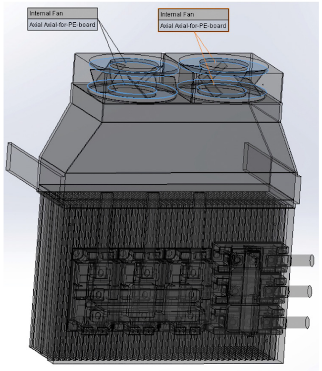
E-Cooling performs thermal and airflow design with FloEFD from Mentor, A Siemens Business. One of its recent designs involved the overall cooling of a 2.2MW frequency converter enclosure. Such converters can be used for a wind power station to provide the grid with the correct frequency or for an electrical drive in order to control the rotation speed. This power is reached by two frequency converter boards, and each has three IGBT power modules and two dedicated axial fans. Each board dissipates 1,350W.
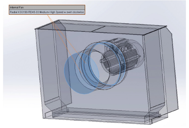
When integrating electronic systems into an enclosure, it is important to determine if there is enough airflow through all critical components. This requires the accurate representation of all the significant flow obstructions as well as the fans. In E-Cooling’s design, each fan and the dust filter were modeled using characteristic performance curves (pressure vs. volume flow) provided by the manufacturers. From the analysis, E-Cooling was able to determine the flow distribution within the enclosure and make any design modifications to allow the necessary airflow for each component, including the use of alternative fans.
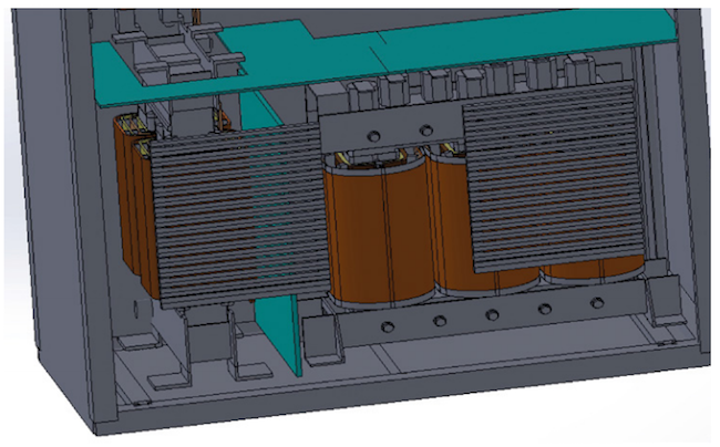
In the lower portion of the enclosure the model detail was not compromised. A detailed representation of the choke and auxiliary transformer was included as well as the flow diaphragm flow upwards and the exhaust grid flow downwards. A critical requirement of the design involved ensuring that a large amount of the flow went through tiny passages between the windings. This could only be realized by obstructing the flow with a diaphragm or inner walls.
Benefits
Designing airflow and cooling solutions at the room level for power electronics is essential to ensuring reliability. During a development project the electrical requirements and losses usually change and components are likely to be replaced. With FloEFD embedded in the MCAD program, the automatic Cartesian meshing, and the option to start a calculation with an initial field, E-Cooling can very quickly update thermal and flow models to meet project datelines.
About the authors
Karim Segond is the founder of E-Cooling, a Berlin-based engineering consultancy specializing in 3D thermal and flow analysis as well as enhancement and development supporting electronics, electric engines, and power electronics.
John Wilson is a Technical Marketing Engineer at Mentor, A Siemens Business.
 Karim Segond is founder of Berlin-based consultancy E-Cooling. His co author, John Wilson, is a Technical Marketing Engineer at Mentor.

