Achieving more efficient hierarchical DFT for Arm subsystems
Hierarchical DFT has wide usage in semiconductor devices because it is the most sensible, predictable, and reliable approach to testing large devices. However, there are various ways in which designers can implement hierarchical DFT, so having a complete, proven reference flow to follow gets the process moving without delay.
Mentor worked with Arm to demonstrate an effective hierarchical DFT methodology on an Arm subsystem comprised of multiple Cortex A-75 cores. The flow demonstrates how to implement the hierarchical DFT methodology while adding very little additional logic and achieving very high-coverage ATPG. This methodology can be applied to other Arm subsystems.
We used the Tessent platform to perform all DFT insertion and ATPG at the block level, then retargeted all the block-level DFT logic and controls, and patterns to the top level of the design.
Why use hierarchical DFT?
Design sizes increase, more fault models are needed for advanced nodes, and the number of IP subsystems multiplies. But the time, cost, and quality requirements do not soften. Finding more efficient methods of design and test is paramount. Thus the hierarchical, divide-and-conquer approach to DFT is becoming standard in many design houses.
Numerous published case studies show the benefits of hierarchical DFT which generates patterns at the block level and directly reuses those patterns at the top level. Some of the foremost are:
- An up to 10X performance gain in ATPG, diagnosis, and pattern verification;
- An up to 2x pattern count reduction;
- The removal of DFT from the critical path; and
- The enabling of core re-use.
Patterns are generated at the core level with much faster runtimes and less compute resources than would be needed for full-chip ATPG. With the use of IEEE 1687 IJTAG infrastructure, hierarchical DFT is highly automated, flexible, and scalable.
Why use a reference flow?
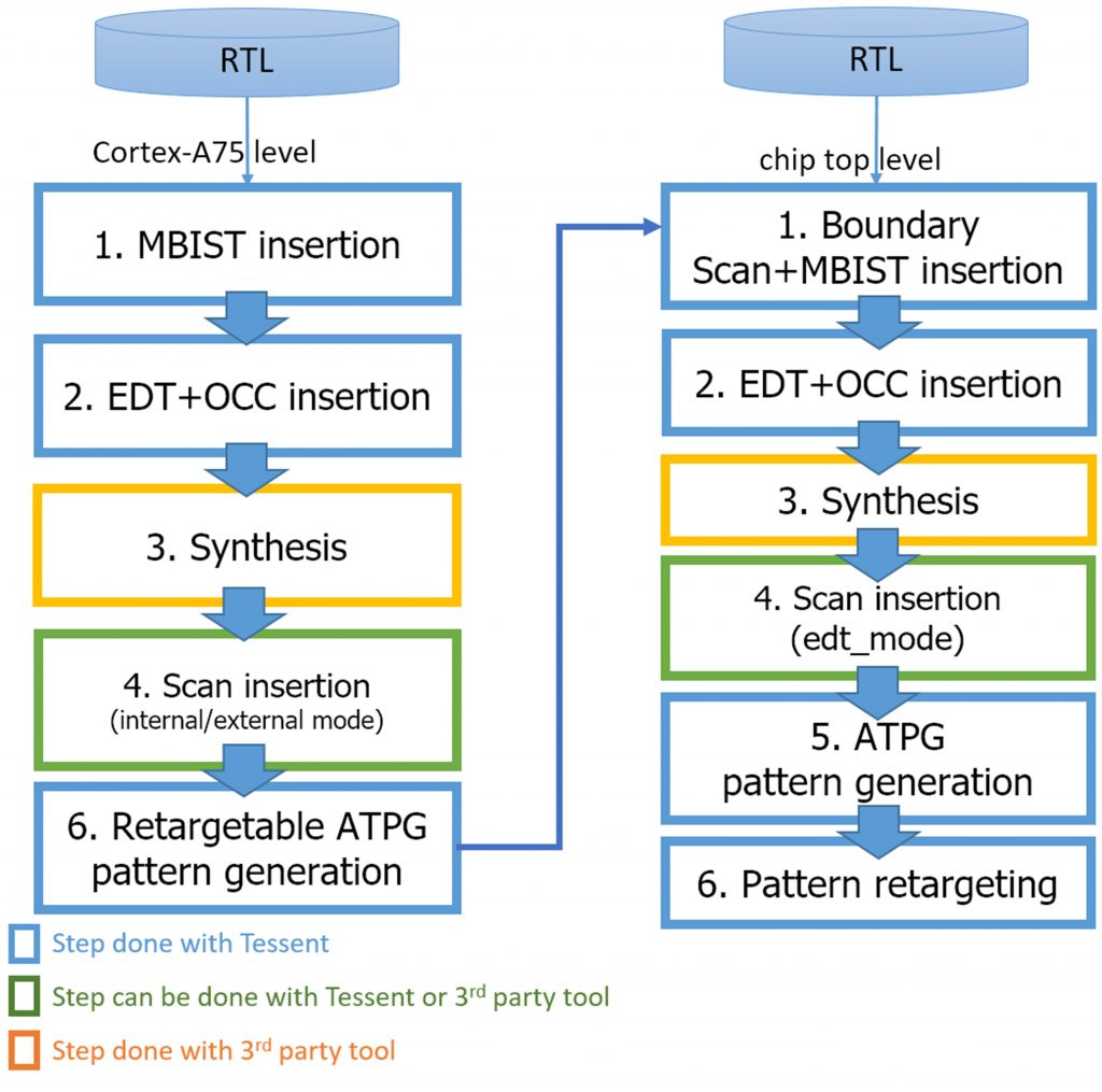
Because there are a number of ways to implement hierarchical DFT, it helps to have a reference flow to get started. This is easier than ever since Arm and Mentor created an RTL-based, hierarchical DFT reference flow. This flow provides a simple and verified hierarchical test methodology for cost-effective, high-quality test of Arm IP, making it easier to reap the benefits of hierarchical DFT. The flow defines all the steps necessary to implement RTL-level hierarchical DFT, including scripts, interfaces, and documentation. Figure 1 shows the flow chart for hierarchical DFT on the Arm Cortex-based reference design.
About the hierarchical DFT reference flow
In the Arm/Mentor DFT reference flow, two levels of DFT are implemented: one for wrapped Arm Cortex-A75 cores and the second for the top-level design. Any similar type of subsystem with Arm cores can refer to this flow. The reference flow contains memory BIST (built-in self-test), IEEE 1149.1 boundary scan, an on-chip clock controller (OCC), and embedded test compression (EDT) for pattern compression and flexible test access mechanism (TAM) ensuring the best channel resource utilization.
It is a bottom-up flow, starting with RTL-based memory BIST insertion in an Arm core, followed by EDT and OCC insertion. After DFT insertion, synthesis and scan cells are inserted, along with wrapper cells. The wrapper cells allow the cores to be seen in a graybox view during top-level test. The graybox view is a lightweight model that only includes wrapper changes that isolate the core logic. After synthesis and the insertion of scan and wrapper cells, ATPG is performed. During ATPG, the grayboxes are generated, along with stuck-at or transition pattern sets that are retargetable to a higher level of the design hierarchy. For duplicate blocks such as the Arm core in a subsystem, the DFT insertion and pattern generation only needs to occur once. Then the results are automatically mapped to each instantiation of that core.
For the top-level design, the first DFT insertion pass includes the following:
- A JTAG compatible TAP controller;
- Boundary scan logic;
- A Memory BIST assembly module for shared bus memories in the chip top level; and
- IJTAG-based memory BIST for individual memories
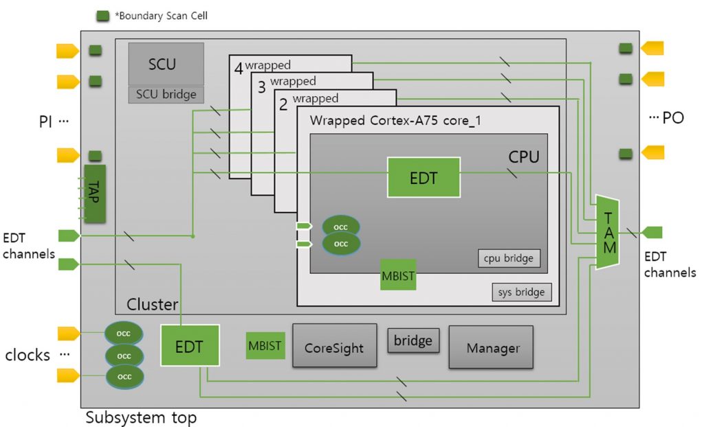
A second DFT insertion pass adds EDT logic and OCCs to the top-level design. Based on the scan configuration, a test access mechanism (TAM) is added. A diagram of the design with all DFT logic inserted is shown in Figure 2.
Next follow top-level synthesis, scan insertion, ATPG, and ATPG retargeting.
Summary
Hierarchical DFT is now standard procedure for most large IC designs because it effectively reduces DFT effort, minimizes ATPG runtime, and still achieves the target test coverage. Mentor and Arm have made it easier to adopt an RTL-based, hierarchical DFT methodology for SoCs that use Arm cores by creating a complete reference flow.
Further reading
For more information, download this whitepaper: “Tessent Hierarchical ATPG Reference Flow for Arm Cortex-A75”.

