A ‘blue book’ for PCB designers
Most of us would never buy a car without poring over online reviews, ratings, expert reviews, and valuations. We might read up on how to negotiate with dealerships. In fact, some of us take similar steps when shopping for a lot of things: be honest, how many reviews did you read before buying that new case for your smartphone?
All kidding aside, this is a smart way to buy. Of course, you are going to apply even more diligence and rigor when evaluating new PCB design solutions. And just as with your new automobile, you know that price is only one factor. Even more so than for most consumer goods, in EDA, the tool’s differentiating qualities and capabilities, more than its price tag, save you more time and money in the long run.
Clearly, PCB design tools come with different capabilities and can be targeted for different product spaces. Most importantly, choosing the wrong tool for your designs can cost you dearly in terms of time, profits, and even the health of your business. So it is essential that you fully understand the cost-performance measurements for each aspect of the products you are considering.
For example, if your PCB design tool has a unique capability or functionality that can eliminate even a single PCB prototype build or respin, any price difference can quickly become insignificant. Likewise, if a design tool has capabilities that enable you to accelerate the design cycle by as little as 10 percent and gets your product to market faster than a competitive tool, that can quickly make a price difference irrelevant.
Don’t worry, we’re here to help with a buyer’s guide to help your company choose the right PCB tools for your design environment and product markets.
Seven tips for buying a PCB design tool
- Adopt tools that can make your products best-in-class
The PCB design tools you select should have the features and functionality that will help you make sure your products are best-in-class. That is, the tool flow must allow your products to be designed optimally, reliably, cost effectively, and in a single pass.
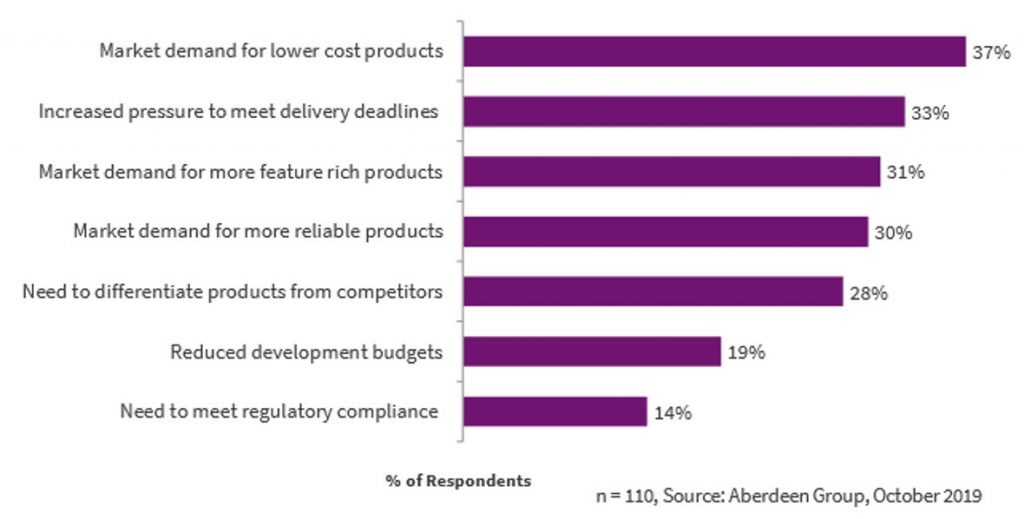
The leading motivations for improving PCB design, according to a November 2019 Aberdeen study, are shown in Figure 1.
To meet these pressures, companies need PCB design tool features and capabilities that reduce product cost, accelerate time-to-market, and ensure product reliability in their electronic product’s space. For example, in the cellphone market you know that product dimensions, physical interfaces, buttons, and screen locations are all influenced by the competition and the consumer. The end-market demands, a PCB tool with features including MCAD collaboration, rigid-flex, and RF centric design capabilities, along with an ability to simulate and address possible signal integrity, power delivery, and thermal issues.
- Size PCB design tools to fit your products
As the spectrum of PCB design complexity is very broad—from very simple, inexpensive, single and double-sided PCBs to highly complex, high-density, multi-layer, mixed-technology systems—so is the range of PCB design products. Thus, PCB design tools are developed with various levels of functionally and cost targets to support different product markets.
Determining the tool flow that fits your specific product space is critical so that you have access to all the functionality your designs require. Likewise, selecting a PCB design tool that is too complex for your designs can unnecessarily complicate and delay design.
There is a vast array of design tools—from freeware tools created predominantly for makers and hobbyists to the enterprise tools (aka enterprise application software (EAS)) used by the world’s leading technology companies. Maker and hobbyist tools are typically easy to use and intuitive. They are best suited for one-off or short run production designs. Enterprise software must contain the sophistication to drive innovation and invention in all areas of electronic design. So step two in a PCB tool purchasing decision is to determine your product complexity and business needs.
- Select PCB design tools that match your business
Keep in mind the technologies your product requires as well as the capabilities, expertise, and challenges in your business when selecting a PCB design tool.
PCB design tool companies in each segment compete by implementing design features and functionality that differentiate their tools from those of competitors and that provide levels of integration that suits their design environment and product market.
From simple PCB design tools created for makers, to tools aimed at desktop, small, and mid-sized businesses, to full EAS solutions, the features and capabilities of each tool vary from market to market and from tool vendor to tool vendor.
Developed predominantly for the student, hobby, hacker, and maker communities, maker PCB tools are available as freeware or at very low cost. They are best for making PCBs that are single layer or essentially simple and straightforward designs with only a few layers. So, they are typically limited in functionality but intuitive and easy to use.
Small electronics design companies will need a few more PCB design tool features and capabilities. Such tools typically support more layers, pad and shape definitions, better manual routing, some levels of properties and net management, pre-made libraries, and online technical support. They typically lack features like schematic-layout integration, constraint management, rules-driven place-and route, yet are suitable for creating small products.
Medium-sized businesses usually need the horsepower to design complex PCBs without the infrastructure demands and challenges associated with an enterprise tool. These are typically self-contained, integrated, full PCB design flow tools that support hardware engineers and small workgroups. With support for FPGA design, enhanced RF, rigid-flex and high speed design, MCAD collaboration, part and model libraries, and more, these tools generally have or can provide access to the advanced features and capabilities required to design todays modern electronic products.
Enterprise tools not only provide access to all PCB design capabilities, but also support the level of integration required to address all the complexities of working across big design teams, even those spread throughout the world. The enterprise design flow helps large companies more efficiently leverage design team resources and manage intellectual property on a global basis by supporting things like IP management, supply chain integration, and design team coordination across multiple divisions and sites.
- Compare the differences between PCB design tool features
Ensuring that your electronic product can be designed in any PCB design tool flow may very well require taking the time to evaluate and benchmark competitive tools. The aim of benchmarking is not to determine mastery of the tool but rather to identify the product’s strengths and weaknesses and use that information to ensure you are making the correct product selection.
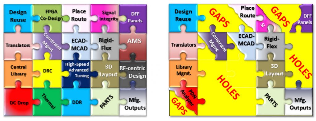
There are unique and specific ways that different PCB tools approach design. Same-named operations, like routing, that seem intuitively straightforward can be vastly different from design tool to design tool. Capabilities like rigid-flex, radio frequency, MCAD collaboration, simulation, and validation are other areas in which PCB design tool features and capabilities are not created equally, can prove unavailable, or may require third-party tools to accomplish.
Understanding the PCB’s technologies and execution is extremely critical when selecting a design tool. Companies that do not fully consider all of their product’s design requirements and later discover the design tool they have selected falls short, will see detrimental impacts on their product’s cost, performance, and time-to-market — even on their business.
- Pick a tool that can ‘shift left’ your methodology
The goal of the shift-left design philosophy is to move as much verification as possible to as early in the design cycle as permissible, while also automating analysis to provide the highest possible degree of coverage. Identifying and correcting issues at the source eliminates time consuming debug efforts and costly respins. It is a more efficient process that provides more predictable results, eliminates design respins, and yields higher quality products in less time.
When we rely on physical prototypes or sophisticated simulation tools to verify designs late in the design cycle, simple errors that should have been caught earlier can require weeks of effort to identify and fix. Though many companies accept this as an inevitable result of increased product complexity, it does not have to be that way. Product creation and PCB design flows as a whole have evolved over the past decade. We have gone from a linear approach – where a single, simple mistake can derail a project and cost thousands, even millions of dollars – to a design flow based on the shift-left methodology that is more intelligent, accelerates design cycles, and ensures product reliability and performance.
Within this PCB design methodology, verification tools are integrated throughout the design process, enabling designers to find and fix errors where they happen, instead of waiting until later in the flow. This is accomplished with automated verification tools that are part of the design process, instead of forcing designers to run separate tools. Analysis is run automatically and users are immediately presented with issues to investigate and fix if needed. This means basic errors are caught and fixed before they have a chance to propagate and cause other problems, making the whole design process more effective and predictable.
The shift-left solution integrates a broad range of analysis and verification tools during the schematic and layout phases of the project. These tools are aimed at non-specialist PCB design engineers and layout designers, allowing them to work within familiar authoring environments to identify problems early in the design cycle.
- Create a tool flow that supports early and frequent collaboration across disciplines
There are numerous design challenges in electromechanical systems that cause issues that can affect both the electrical and mechanical domains. A PCB design flow that supports electromechanical collaboration ensures that both domains are synchronized to enable consistent, iterative communication between design disciplines. This is essential to productivity, product success, eliminating electromechanical respins, and reducing product costs.
A design flow that allows design engineers or teams of engineers to simultaneously work together to create an electrical design from schematic through to PCB is exponentially faster than if each step is done by one person at a time. Similarly, a mechanical engineer or team can collaboratively utilize electronic data transfer information to simplify the start of a PCB design and make traditionally time consuming engineering changes in just a matter of minutes.
In modern electro-mechanical designs, tight synchronization between the electrical and mechanical flows is required to ensure that both design domains are correctly aligned for fabrication, which ultimately decreases the design effort and accelerates product time-to-market. Today, many companies still utilize the traditional Intermediate Data Format (IDF) to transfer information between electrical and mechanical systems, versus a more advanced MCAD collaboration.
- Make sure your PCB design solution Is scalable
From the earliest stages of an electronic product’s definition and functional specification, all of the product’s hardware design requirements and complexities must be fully understood . Thoughtful consideration of a product’s evolution helps in determining a PCB tool design flow or environment that not only accomplishes your design needs for today but tomorrow as well.
Regardless of the size of your tech company, the number of designers/engineers working on a project, or the complexity of a design, you need a PCB design tool flow that provides the appropriate capabilities as they become necessary. This kind of scalability is needed not only to move designs from conception to manufacturing but also to transition and support designs when a maker requires a desktop tool, when a start-up company grows from a small to a mid-sized business, or when a small or mid-sized company becomes the next Fortune 100 company and requires a fully integrated enterprise design environment.
By following these seven tips, we think you will end up with a PCB solution that will help you succeed, and make your design team’s life easier…and hopefully make at least one of your buying decisions less stressful. We also offer more insights and information on picking the right PCB tools for your flow based on this ticklist in this whitepaper: 7 Things to Consider Before Selecting a PCB Design Tool.
 John McMillan is a Technical Marketing Engineering Manager at Mentor, A Siemens Business. He has over 30 years of experience within the EDA industry. He’s a seasoned PCB designer and held key positions within the EDA industry including Principle ECAD Engineer, and Applications Engineer in fields such as technical management and R&D.

