Verifying clock domain crossings in UPF-based low-power SoCs
This article discusses the verification challenges of using low-power design techniques to enable advanced power-management strategies in complex SoCs. These techniques can introduce critical bugs into a design, especially when the power-management infrastructure interacts with signals that cross clock or reset domains. This can create additional clock-domain crossing (CDC) paths, or break the synchronization of pre-qualified CDC paths. The result is complex bugs that traditional CDC tools cannot address. The solution is a new approach to CDC verification and signoff.
What is a CDC problem?
Many digital IC designs use a universal clock signal to synchronize their operation, ensuring that the state of a changing logic signal is only sampled once it has settled to its new value. Power-management techniques can introduce multiple independent clocks, which in turn means that signals have to be synchronized when they cross between clock domains. Otherwise, asynchronous clock signals can reach different flip-flops at slightly different times in each cycle. This timing uncertainty can cause random set-up and hold-time violations in the design, which lead to meta-stabilities that cause functional failures.
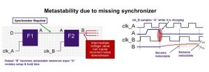
RTL CDC tools such as SpyGlass CDC can report violations at the RTL level and ensure that proper synchronization is added to a circuit. Figure 1 shows how two functions, driven by separate clocks, can become metastable if the signals between them are not synchronized in some way.
Figure 1 The lack of synchronization between clock domains can cause metastability (Source: Synopsys)
How power-aware designs can cause CDC issues
Power-aware designs, which use common low-power design techniques such as power shutoff and multiple voltage domains; and advanced techniques such as dynamic voltage and frequency scaling, low VDD standby, and biasing, rely on hardware features such as isolation logic, retention cells, and power switches. Designers also use a Unified Power Format (UPF) file to define their strategies for isolation, retention, and level shifting in their designs.
Designers usually specify their power-management strategies in the design’s RTL. The increasing complexity of these strategies leads to UPF specifications that include a large number of power state tables (PSTs) and define multiple power domains. The UPF file should disallow conditions in which global signals (such as clock, reset, and test_enable) or control signals (such as isolation and power-switch enables) cross from a source domain to a sink domain. The UPF should also disallow the source domain ON condition becoming a superset of the sink domain ON condition. If any of these conditions exist in the design, they can cause functional issues because when the source is OFF, a signal cannot reach its destination domain. Trying to find and fix these issues using dynamic simulation techniques and manual debugging of multiple PSTs can be very time consuming and inaccurate.
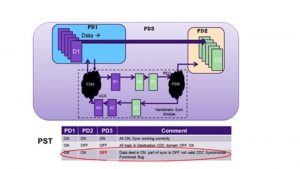
Figure 2 shows a design to which power management-techniques have been applied. Before the design was broken down into separately managed power domains (PDs), the signal path from D1 to D2 was directly synchronized using a Handshake Sync Module and so the RTL didn’t have any CDC issues.
After the insertion of low-power cells and the definition of PDs in the PSTs, the path from D1 to D2 becomes a power-aware CDC path. This is because the source (D1) is now in PD1, the sink (D2) is in PD2, and the synchronization signal comes from the Handshake Sync Module in PD3.
Based on the PST provided in Figure 2, if PD1=ON, PD2=ON, and PD3=OFF, data can still be transmitted from D1 to D2 without synchronization by the Handshake Sync Module. This makes the crossing between power domains asynchronous and so causes a functional bug.
Figure 2 A CDC path with its qualifying signal in a different power domain (Source: Synopsys)
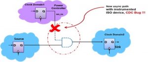
Let’s take another scenario, as shown in Figure 3, in which a source flipflop and a sink flipflop are initially in the same clock domain, ensuring that the path between them doesn’t have any CDC issues. Once an isolation cell has been inserted between them as part of a power-management strategy, an asynchronous path is created from clock domain 1 to clock domain 2 causing a CDC bug.
Figure 3 Inserting an isolation cell to manage power creates another CDC path (Source: Synopsys)
UPF-aware CDC verification
This issue cannot be solved by either CDC tools or low-power verification tools alone. It needs a CDC analysis that is informed by the UPF, supports real-time instrumentation of the design, interprets the UPF in the same way as the implementation tool, and enables incremental CDC verification on new logic paths introduced by the power-management strategy.
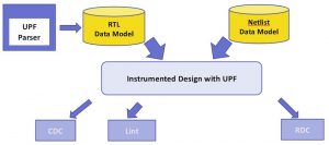
As shown in Figure 4, the UPF-aware static verification solution should perform the CDC analysis on the UPF-instrumented design to flag issues that arise due to the UPF instrumentation, along with any traditional CDC issues. The static analysis can also extend to other solutions such as lint and reset-domain crossing analysis.
Figure 4 A UPF-aware CDC solution (Source: Synopsys)
Power-aware designs have additional design verification challenges. Existing tools and methodologies are insufficient for confident RTL signoff, because power-management strategies can introduce new logic and signal paths. A UPF-aware static solution is necessary to catch all the issues introduced by the power-management logic. The UPF instrumentation should also be in sync with downstream implementation tools, and consistent in supporting the latest constructs.
Author
Rahul Chirania is a staff applications engineer with the static verification team at Synopsys. He has more than nine years of experience spanning in the electronic design automation and semiconductor industry, including in ASIC design and verification. He is currently working as a CDC/RDC product specialist to help designers define and refine their CDC/RDC verification methodologies.
 Rahul Chirania is a staff applications engineer with the static verification team at Synopsys.


