Three ways to lift productivity during physical verification
How to get the best PV results by reducing computational demands; handling data more efficiently and exploiting parallelization.
Physical verification can seem tedious and time-consuming, but it is where your design starts to come to life. ‘Can I manufacture this layout?’ ‘Will it perform as it’s supposed to?’ ‘How can I tweak it to achieve the best results?’
Given the importance of physical verification, companies devote a lot of time and resources to this stage of the design flow. That can feel overwhelming. The increase in geometric data volume from one node to the next, and a corresponding increase in the number and complexity of design rules have driven exponential growth in computing demands and tool functionality across verification flows. Making sure you use all your resources in the most efficient way possible helps ensure you have optimized both your tapeout schedule and the bottom line.
In general, design cycle planning is based around full-chip design rule check (DRC) runs that complete overnight. The actual DRC runtime can vary from 8 to 12 hours, but the basic idea is that completing it ‘overnight’ leaves the next day to implement corrections for identified errors. This cycle repeats until tapeout.
Managing physical verification runtimes is a multi-dimensional challenge. We primarily use three strategies to keep DRC runs to an expected duration for each process node:
- Reduce the computational workload by optimizing the rules and checking operations.
- Handle data more efficiently with newer database standards or by adding hierarchy.
- Parallelize as much computation as possible.
Let’s look at each of those in more depth.
Reduce the computational workload
This generally has two components: (1) optimizing design rules, and (2) enhancing DRC tool efficiency, the latter both in general terms and as new functionality is added.
Rule file optimization
In a robust DRC language, there are often multiple ways to describe the same rule. The challenge lies is identifying which one is the most computationally efficient.
This is not as easy as might first appear. For example, because different operations may take different amounts of time to run, promoting the rule implementation with the fewest number of steps does not automatically ensure the fastest possible runtime.
A rule deck contains tool-specific constructs, normally in ASCII format, that describe the algorithms needed to validate geometric adherence to each design rule. The folks tasked with coding the design rule manual (DRM) are typically foundry experts in their companies’ process requirements, but they do not always have expertise on the inner workings of the DRC tools they use to establish the accuracy and coverage of the new rule deck. Using best practices, the EDA DRC tool supplier can provide an initial set of suggestions back to the foundry to help optimize rule performance. At the same time, initial DRC results from the first design teams exposed to a new deck can help identify potential performance bottlenecks.
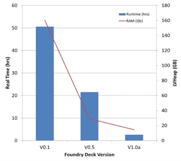
The suggested optimizations and feedback must be carefully reviewed by the foundry’s rule-writing team. Proposed rule changes that improve runtime without impacting accuracy are included in the next revision. Figure 1 shows the typical improvements that can be achieved when the tool supplier and foundry rule-writers collaborate to optimize rule files. As the development of the DRM and the associated DRC continues, enhancements are periodically made available to the early adopters with new releases of the DRC tool, providing a constant feedback loop embracing designers, the tool supplier, and the foundry. As greater maturity accrues through test chips and sample designs of increasing complexity, the process becomes relatively stable and a more formal production rule deck can be released.

Figure 1. Rule file optimization is a collaborative process between foundry and sign-off DRC tool supplier
DRC engine efficiency
The next way to reduce computational load is to modify the DRC tool itself. For each node, the EDA tool supplier must enhance and modify the DRC toolset to address the design and runtime challenges that are inherent in new technologies. Some EDA companies also invest a significant amount of R&D resources to constantly ensure their tools run faster, use less memory, and scale more efficiently at all nodes.
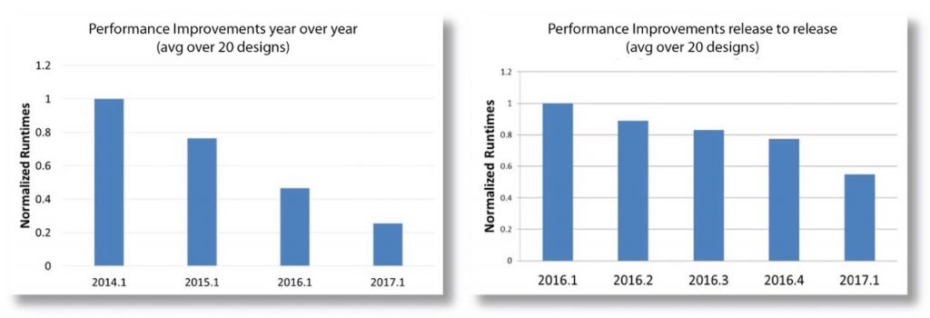
Figure 2 shows the typical rate of runtime improvements that an engine optimization can deliver. In this case, runtimes for the Mentor Calibre nmDRC tool were measured across several releases and more than 20 large SoC designs targeting processes at or below 20 nm. The runtimes were averaged to illustrate the expected runtime improvements for typical designs.

Figure 2. DRC engine optimization improves performance year-over-year and from release-to-release (click to enlarge)
New functionality efficiency
When new functionality, such as multi-patterning technology, is introduced, it must be optimized to ensure the best possible performance. However, this optimization is not a onetime process. Just as with engine optimization, the tool supplier continuously evaluates and refines the functionality.
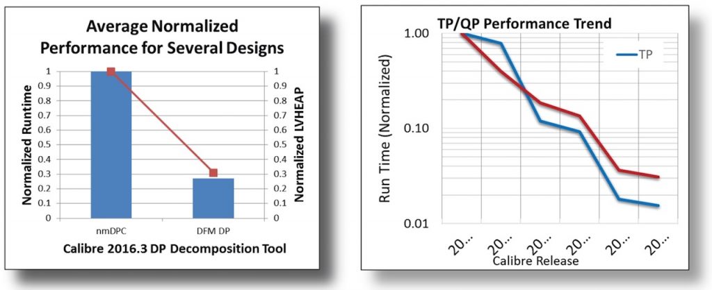
Figure 3 illustrates the runtime improvement achieved over time for multi-patterning processes at Mentor. When double patterning (DP) was first required, it was performed as part of the resolution enhancement technology (RET) toolset used by foundry engineers. Over time, as more multi-patterning techniques were introduced, responsibility for multi-patterning decomposition and verification shifted to the design side, and automated multi-patterning tools for designers were created.
At Mentor, we used what we learned from the foundry-side process to reduce runtimes through increased scaling (including native hyperscaling) and increased remote CPU utilization. At the same time, we optimized performance by reducing memory usage and improving the utilization of hierarchy.

Figure 3. Improvement gained by re-implementing foundry-side DP functionality in a design-side tool (left) vs overall runtime performance trend for multi-patterning (click to enlarge)
Data management efficiencies
Database format
Not surprisingly, the choice of database format can have a significant impact on data transfer and file I/O during design, the handoff to manufacturing, and manufacturing itself.
During design, data is passed from the layout tool into physical verification. It is critical here that the format fed into the verification tool is consistent with the data format used by the target foundry. By eliminating the need for a data format translation at tapeout, a design company eliminates the chance introduction of translation errors as well as the extra time translation requires. It is then important to remember that a physical verification tool often generates new layout data, such as fill, so data consistency is also important during the design iteration phase.
Once a design is clean and ready for manufacturing, it is transferred electronically to the foundry. The GDSII format has historically been the format of choice but it has more recently encountered syntactic limitations that adversely impact file size. File size dictates how quickly such data can be shared, and the continuing growth in design database sizes has led to slower transfer times.
Foundries have begun adopting the OASIS format as an alternative. Unlike GDSII, OASIS is configured to minimize redundancy when describing geometric patterns. It can offer anywhere from a 10X to >100X reduction in file size, significantly reducing internal iteration read and write times.
Data hierarchy
Another way to improve computing efficiency during physical verification is by optimizing with respect to the layout data to be checked. A great example of optimizing based on data patterns is the use of hierarchy. If a design contains a cell or block that is repeated several times, significant computation time can be saved if the DRC tool checks each unique layout pattern only once, then checks the relationship of each pattern instantiation to its surrounding objects. The goal is to produce the exact same results when checking hierarchically as if the checks were done flat (i.e., with no recognition of repetition), and get results much faster.
Fill data optimization
A good example of the benefits of hierarchy for physical verification can be observed in the handling of fill data. At advanced processes, fill must be added to essentially any open space in the layout where it can fit without breaking design rules. However, the increased use of fill and the specific fill methodology affect both fill runtime and file size.
Traditionally, fill was left until just before tapeout. Following this approach, filling is performed at the chip level, which can (and usually does) have a significant detrimental effect on DRC runtimes. A DRC tool must check design rules (e.g., spacing between shapes) for fill, as well as the native design shapes. Unfortunately, the fill shapes are not in the same hierarchy as the design, and typically cannot be captured as repeated patterns because the fill is inserted without regard to the original hierarchy. This limitation means the only way to check millions or billions of fill spacings is in flat mode at the full- chip level. That can be painfully slow.
File size is also a critical factor. It has an impact on runtime, on your ability to move fill databases between design and place and route (P&R) environments, and ultimately on your delivery of a tapeout database to the foundry for mask generation. Designers must implement multi-layer fill shapes for both the front-end-of-line (FEOL) base layers, and back-end-of-line (BEOL) metal layers.
The FEOL rules include fill shapes that must maintain uniform density relationships across multiple layers to reduce the variability created by rapid thermal annealing (RTA) and stress. To further reduce the manufacturing stress and provide structural stability, BEOL fill incorporates dummy vias, which must also satisfy multi-layer rules.
Alongside the complexity of the new fill rules, the number of individual fill elements is also increasing dramatically with each new technology. All these factors create huge GDS files that take longer to transfer and process. Many design teams have given up on the idea of bringing billions of fill shapes back into their P&R environment simply because of the impact on their P&R systems.
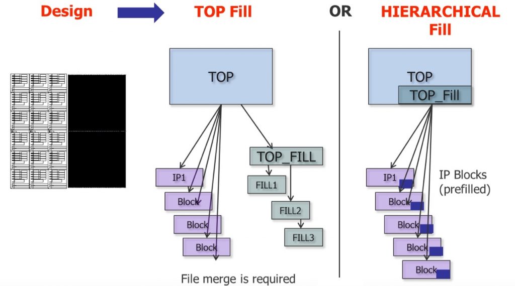
One solution is to raise the level of abstraction by moving from individual polygons to a cell-based fill solution, defining a multi-layer pattern of fill shapes that is repeated in many places across the chip (Figure 4).
Fill cells are a natural extension of the multi-level fill constructs that must be maintained, and can be used for both FEOL and BEOL. Designers add fill at the block level first for any large block that is placed more than once. When the chip is assembled, the fill is consistent for each placement of that block. This technique has the added benefit of providing a more accurate assessment of the block’s performance, since the effects of fill parasitics are included. Fill is also applied at the top level to cover any areas not addressed by pre-filled blocks. This ‘fill as you go’ technique allows hierarchical tools to check the fill within the block only once, not for each placement, reducing post-fill runtimes by a factor of more than four.

Figure 4. Hierarchical fill provides a number of productivity benefits in the design flow (click to enlarge)
The cell-based approach to fill provides benefits for both runtime and file size. Using the OASIS format also allows this approach to be used with all P&R tools.
Parallel processing
Even with well-optimized rule files and data handling strategies, and the latest DRC tool version, it is still impossible to complete a full-chip DRC run overnight without taking advantage of parallelization. Physical verification raises two particular challenges: the volume of layout data, and the computational complexity of the rules. Fortunately, they can be effectively addressed with parallelization to help ensure fastest total runtimes.
Parallelizing the layout data to be checked means that as one CPU checks the geometries of a layer associated with one cell, another CPU checks the same rule on the same layer, but for a different cell. This maximizes the use of shared memory, largely eliminating the memory contention associated with single-CPU runs.
Parallelizing the DRC checking operations in a rule file allows any two rules to be run on separate CPUs in parallel. Since all input layers for each of the parallelized operations must be available, any operation requiring a derived layer on input must first wait until that layer has been derived. Once the layer has been derived, all operations dependent upon it can proceed.
Both of these approaches can take advantage of multiple CPUs on the same machine, or CPUs distributed over a symmetric multi-processing (SMP) backplane or network. Tool suppliers also develop run environments that can offer even more optimization. For example, the Calibre platform from Mentor can use virtual cores, or ‘hyperthreads’, which provide about 20% of the processing power of a real CPU. The Calibre platform also takes advantage of memory on distributed machines, which helps reduce the total physical memory required on the master system. This approach is known as hyper-remote scaling, and is the recommended best practice for full-chip DRC sign-off runs at advanced nodes.
Enhancing physical verification
Productivity in physical verification requires multiple strategies and technologies. Companies who want to ensure they are maximizing the value of their time and resources must carefully and continually evaluate both their process flows and the tools they use.
Reducing the computational workload, optimizing data management, and employing parallel processing technology allowing design companies to deliver innovative, reliable, and profitable electronic products to an ever-expanding marketplace at greatest efficiency.
Further reading
Achieving Optimal Performance during Physical Verification
About the author
John Ferguson is the Director of Marketing for Calibre DRC Applications at Mentor, a Siemens Business, in Wilsonville, Oregon and specializes in physical verification. He holds a BS degree in Physics from McGill University, an MS in Applied Physics from the University of Massachusetts, and a PhD in Electrical Engineering from the Oregon Graduate Institute of Science and Technology. He can be reached at johnUNDERSCOREfergusonATmentorDOTcom