Silicon photonics verification: Progress through adaptation
SiP promises advances in transmission speeds, bandwidth, accuracy and low power but verification requires careful evolution of existing tools.
The growing desire to gather and manage data requires innovative techniques to transmit this data with tremendous speed while using much less energy than conventional methodologies. The need for effective transmission strategies is one of the main drivers for the exploration of various cutting-edge technologies, among which is silicon photonics (SiP). The main goal of photonics integrated circuits (PICs) is to use light to perform those functions that are typically done using electronics. SiP technology is rapidly gaining traction in multiple industries and applications from medical diagnostics to telecommunications to automotive and manufacturing. This is due in large part to SiP’s ability to perform functions like data transmission, information processing, and computing with blazing speed and extremely high accuracy, while consuming minimal power.
The overall IC market has had to overcome many challenges throughout its history, most recently in moving to leading-edge process nodes. A solid contributor to its success in conquering these challenges has been the EDA automated verification platform. It helps design companies and foundries ensure manufacturability and proper functionality. Its existence allowed the rapid development of the thriving CMOS technology.
To reap the benefits of SiP technology and enable it to grow in a similar fashion, it seems logical to reuse the CMOS platform (particularly that automated verification EDA toolset) to duplicate earlier success. However, this effort is by no means a simple copy-and-replace process. One of the first challenges is determining which components can be borrowed from the traditional CMOS IC verification platform. These components must then be modified to accommodate the unique requirements of PICs and deliver the desired results.
Silicon photonics verification challenges
Physical verification challenges
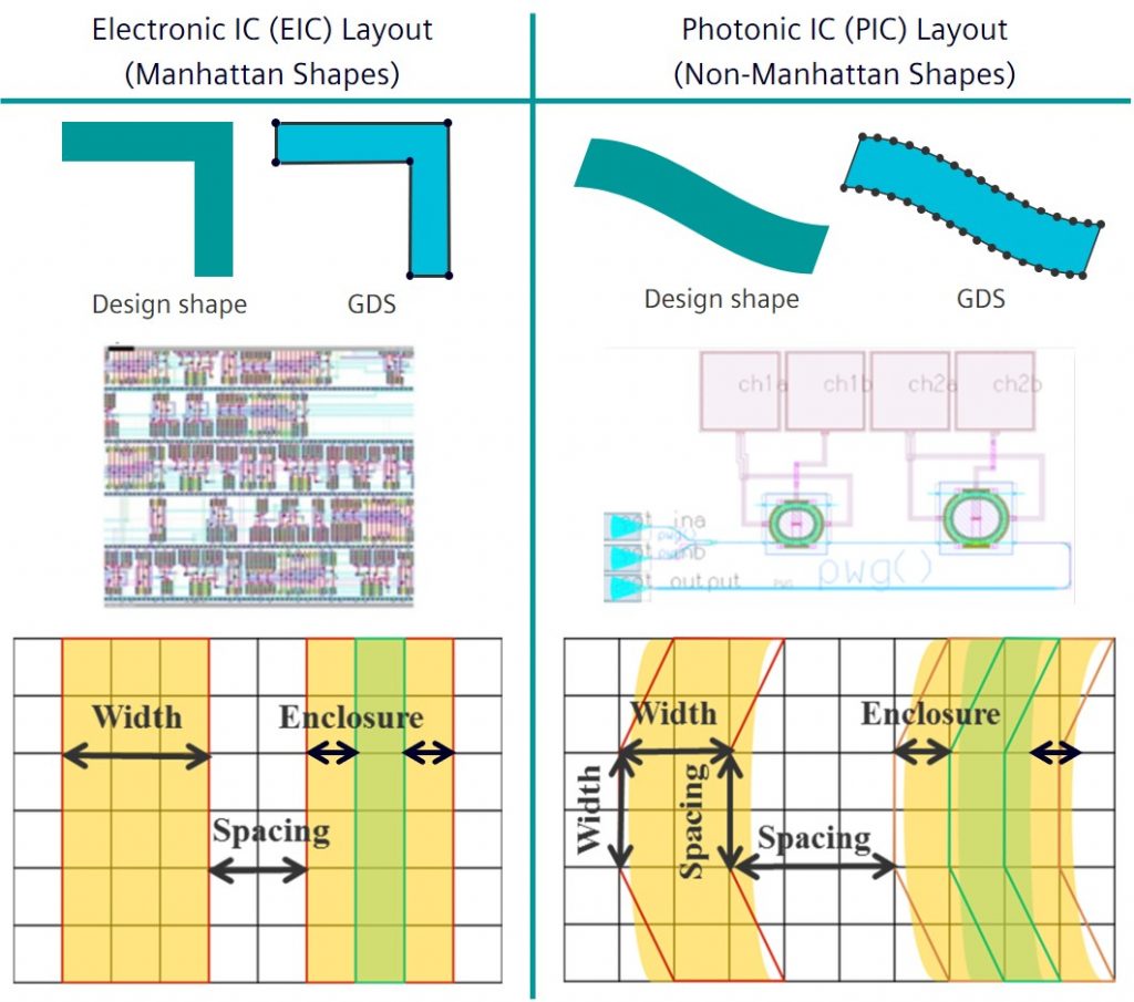
Design rule checking (DRC) is the process responsible for ensuring the manufacturing feasibility of an IC by validating its geometrical integrity. DRC verifies that the physical implementation of the design (the layout) complies with design rules set by the foundry. Traditional ICs use Manhattan geometry, meaning all of the included shapes are designed in an orthogonal manner and placed on a rectangular grid. Individual checks include various measurements performed on shapes in the design (e.g., the length of a transistor gate). Because these designs consist of Manhattan shapes, the measurements present no problem when the layout is built on the conventional rectangular grid.
PICs, on the other hand, are characterized by curvilinear, non-Manhattan like features. A wide range of PIC structures include curves such as ring resonators, ring modulators, bend wave guides, directional couplers, and grating couplers. Current layout file formats like GDS or OASIS, with their rectangular grids, do not support such curved structures natively.
Placing curvilinear structures on a rectangular grid presents a challenge for existing DRC verification tools and processes. When analyzing PIC layouts, the current EDA toolset must perform an approximation of some sort to deal with these basic photonic components. For example, in the Calibre nmPlatform, a piecewise linear approximation methodology is adopted, in which the curve is divided into edges and those edges are then fitted on the existing grid points (Figure 1). Unfortunately, any kind of approximation results in some degree of snapping, as well as false DRC violations.
Precise measurement is problematic due to this edge and vertex snapping which can occur when the vertices of the curved shapes must adapt to the precision of piecewise linear approximation (Figure 2). This effect must be compensated for during the geometrical parameter measurements; otherwise, the design will likely fail to comply with the placed design rules.

Figure 2. Physical verification challenges of curvilinear structures (Siemens EDA – click to enlarge)
Circuit verification challenges
Layout vs. schematic (LVS) verification ensures correct circuit functionality. The traditional LVS process includes verifying proper circuit connectivity, recognizing and extracting all devices, then comparing those devices to the source schematic to ensure that every device is of the right type and has the same geometrical parameters as originally defined. Checking all these aspects guarantees the IC will provide the expected and intended functionality and performance.
The primary challenge of PIC LVS verification is simply the immaturity of the SiP ecosystem compared to the current electronics world. This makes basic phases of classical LVS much harder to perform. These phases include the extraction of devices from the layout, characterizing such devices with their most characteristic geometrical parameters, and comparing them with their equivalents in the source. Unlike a traditional IC, whose basic components are treated as built-in devices in the existing EDA tools, photonic components are not yet natively supported as built-in by LVS tools. Consequently, photonic devices must be treated as custom devices, and new techniques must be adopted to enable the LVS tool to extract them from the layout.
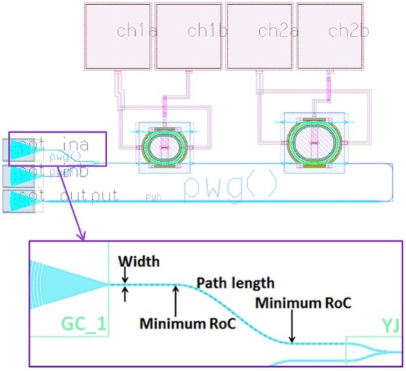
In the traditional LVS flow, one of the main tasks is verifying the connectivity of an IC. At that stage, all interconnects are treated as ideal wires, with no dimensions or parameters to be extracted and validated. This approach is sufficient to ensure there are no unintended shorts or opens, and that all devices are properly connected to one another. However, in a PIC, this basic assumption is inadequate to ensure proper optical connectivity and behavior. Waveguides must be treated as devices because their geometrical parameters have a significant impact when determining proper circuit operation in terms of the modes of propagation of light (Figure 3).
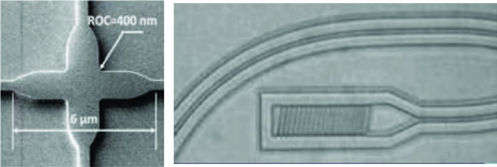
Another key difference between PIC and current electronic IC circuits is the simple concepts of shorts and opens. Wires in an electronic IC should never cross, but two waveguides might overlap in a PIC, creating a four-port network without resulting in a short. A terminator device, commonly used in PICs, does not constitute an open—it simply prevents light from progressing forward (Figure 4).
In traditional LVS, device behavior validation is achieved by calculating certain parameters for each device and comparing those parameters to the provided source. Such parameters are measured based on Manhattan-like geometries (e.g., transistor length). In a PIC, where the devices are of a curvilinear nature, it is much harder to accurately extract such parameters and validate correct device functionality. However, just as in an electronic IC, there shouldn’t be any deviations from the intended shapes, or the photonic circuit won’t behave as expected.
Optical lithography and fill insertion challenges
The incremental technological progress we have witnessed for years fundamentally hinged on Moore’s Law, which was informally adopted by the semiconductor industry as the roadmap for research and development for high-volume production. However, keeping up with Moore’s Law has been a true challenge over the last couple of decades, particularly for optical lithography.
Optical lithography has been the driving force behind a multitude of advances in the IC market to date. Most of these improvements, especially for older nodes, have been implemented on the processing side. However, as we have moved to more advanced nodes, it has become clear that some of the assumptions we relied on in those older nodes are no longer valid. The supposition that what is drawn is what will be delivered no longer holds. As the pitch has continued to shrink, the lithography process has become much more difficult, to the point where the scanner alone can no longer resolve images on the wafer. EDA software has provided the solution, through techniques like optical proximity correction (OPC) that were used to modify the design before the manufacturing process began.
For PICs, accurate modeling of the final shapes of the photonic circuit is crucial because that accuracy impacts the circuit performance. For multi-project wafer (MPW) runs, designers typically require multiple iterations of physical device manufacturing to understand and improve PIC circuit behavior. However, this iteration process can be very time-consuming and carries a high cost.
Another aspect is the fill shape insertion. Fill consists of metal shapes or devices that serve no electrical purpose and are not typically connected to any power source. During the manufacturing of electronic ICs, as each layer is created, the layer is polished using chemical mechanical polishing (CMP) to remove excess materials and ensure a flat, uniform surface. Fill is often added to empty areas in the layout to minimize the chance of peaks or valleys being created during CMP.
While CMP simulation can help designers determine optimum fill insertion, the fill strategy for PICs is a little different. Traditional square fill shapes often cause hybrid modes in nearby waveguides, adding noise to the signal in the waveguide and causing the power to disperse across various modes. Not only is the shape of the fill a contributing factor to dispersion of the optical signal, but fill proximity is no longer just a function in the manufacturing resolution; rather, it is a possible source of electromigration coupling.
Solutions to photonics verification challenges
Inventing an entire PIC verification toolset to accommodate PIC curvilinear structures is unrealistic, given the time and resources that would be required. It makes much more sense to adapt and reuse the existing toolset. This is the route EDA companies have taken.
At Siemens, we’ve developed different PIC verification techniques that can achieve the required degree of accuracy by introducing modest modifications to existing toolsets. The Calibre eqDRC equation-based DRC functionality can apply complex conditional DRC with the necessary tolerance to eliminate false errors in curved segments. Implementing equation-based DRC for PICs does require modifying the foundry rule deck to detect curved edges, and then adding the required tolerances while measuring spacing between them.
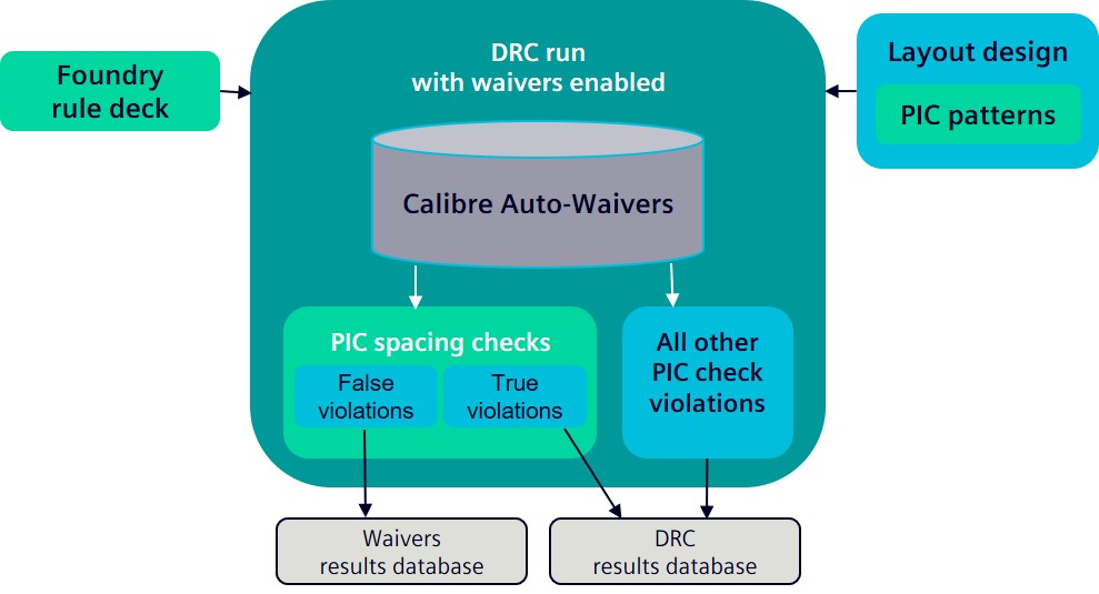
For design companies that shiver at the thought of editing the Calibre nmDRC foundry rule deck, another approach leverages the Calibre Auto-Waivers infrastructure for an innovative post-processing step that filters out false PIC spacing checks violations. The Calibre Auto-Waivers infrastructure can be used to automatically filter out the false violations reported on PIC structures, so that only real violations are reported in the DRC results database file.
In a traditional Calibre Auto-Waivers flow, engineers run Calibre nmDRC checking first, analyze the violations, identify false errors, and generate waivers for these errors that are applied in subsequent Calibre nmDRC runs. With the post-processing approach, engineers perform just one Calibre nmDRC run, in which the false violations are filtered out and saved to a new file, and only real violations are reported back in the Calibre nmDRC result database file. Filtered results are reported in a separate file for review as needed.
The advantages of this technique are obvious: it is fully automated, and it lets foundries use their existing decks as-is, saving the time and effort of adding special equation-based DRC operations for each check in every DRC deck.

Figure 5. Calibre Auto-Waivers post-processing automatically filters out SiP false violations (Siemens EDA – click to enlarge)
As for PIC circuit verification, there have been multiple attempts to find a complete and generic solution to the photonic LVS challenge. Some solutions depend on ignoring the cell contents completely by performing a simple device black box style LVS verification to ensure no shorts or opens exist in the generated layout. This approach is limited in the sense that it does not fully ensure proper matching between the source and the layout devices. Other solutions adopt a different methodology that relies on substantial coding efforts to extract the photonic devices, measure their parameters, and compare them to the devices in the source, while also overcoming the snapping issues. Such solutions are indeed more accurate, but they require substantial time and coding effort, as well as many iterations to reach a final deck that returns correct LVS results with no false violations. The technique employing labels or markers proved to be a step in the right direction in terms of reducing the coding effort needed for the extraction of devices and their parameters, while not sacrificing circuit integrity by ignoring the cell content altogether. However, it can be an incomplete solution in cases where devices overlap, resulting in merged markers.
One promising approach to adequate PIC device verification is simply to re-render the intentional shape to the placement in context. If no changes are found, then designers know the placed device matches the intended source device. There are several techniques that can be used for this comparison, from complex pattern matching to regeneration based on optical equations.
While there are still more challenges to overcome before a complete and broad solution is available for PIC LVS verification, innovative options that repurpose the existing EDA toolset and functionality are continuing to emerge.
Regarding fill insertion for PICs, one solution is simply to use fill shapes with a circular profile, as opposed to squares. This fill recipe can be achieved using Calibre YieldEnhancer SmartFill capabilities, which can optimally insert circular fill around the waveguides.
Over the years, process design kits (PDKs) and the automated design and verification flows that use them have been perfected for the existing IC industry. While complementary PDKs and processes are still in the development phase for the silicon photonics industry, foundries, EDA providers, and design houses are all working in conjunction to create a similar trusted and reliable environment for PIC designs.
Conclusion
Silicon photonics offers up the promise of fast data transmission and high bandwidth, with high accuracy and low power consumption. All of this makes it a very appealing technology for various core fields and applications like today’s high-performance computing, telecommunications, military, defense, aerospace, medical, and research applications. To realize that promise, design companies must have the same trusted level of support provided by foundries and EDA suppliers for the design and verification of electronic ICs. Fortunately, there is no need to reinvent the tools and processes used for today’s mainstream ICs. We just need to expand and adapt them to reach the goal of attaining solid, reliable, automated physical verification and manufacturing verification process flows that address the unique physical characteristics of silicon photonics designs.
To learn more, download the whitepaper “Advancing silicon photonics physical verification through innovation”.
About the authors
John Ferguson is the product management director for Calibre DRC applications at Siemens Digital Industries Software. John has extensive experience in the area of physical design verification. He holds a B.Sc. degree in Physics from McGill University, an M.Sc. in Applied Physics from the University of Massachusetts, and a Ph.D. in Electrical Engineering from the Oregon Graduate Institute of Science and Technology.
Basma Serry is an advanced product engineer for Calibre Design Solutions at Siemens EDA, a part of Siemens Digital Industries Software. Her responsibilities include silicon photonics circuit verification processes. Her previous experience includes work in design rule checking and circuit verification for both electronic and silicon photonic designs. Basma received her BS in electronics engineering from Ain Shams University in Cairo, Egypt.
Omar El-Sewefy is a senior product engineer for Calibre Design Solutions at Siemens Digital Industries Software. Omar received his BS and MS in electronics engineering from Ain Shams University in Cairo, Egypt, and is currently pursuing his Ph.D. at Ain Shams University in silicon photonics physical verification. Omar’s extensive industry experience includes semiconductor resolution enhancement techniques (RET), source mask optimization, design rule checking, and silicon photonics physical verification.
Nermeen Hossam is a product manager in the Design to Silicon division of Siemens Digital Industries Software. Her primary responsibilities are product management for the Calibre Auto-Waivers tool and support for Calibre nmDRC functionality. Mrs. Hossam received a B.Sc. in Electronics and Communications from Ain Shams University, Cairo, Egypt, and an MBA from the Edinburgh Business School of Heriot-Watt University, Edinburgh.


