DRAM interfaces for mobile and networking designs
Mobile and networking platforms need high bandwidth, low power consumption, and small footprint. These needs drove standards, such as LPDDR4, Wide I/O 2 and Hybrid Memory Cube.
For years, the notebook and desktop PCs have driven volume and capacity demand for dynamic random access memory (DRAM) devices. But the rise of the smartphone, tablet and advanced networking platforms is driving even more rapid DRAM innovation. These platforms have stringent requirements in terms of bandwidth, low power consumption, and small footprint. These pressures have led to the development of new memory standards optimized for the different market niches within the smartphone and tablet markets.
For example, rendering the graphics in a typical smartphone calls for a bandwidth in the range of of 15GB/s. This is a rate that a two-die Low-Power Double Data Rate 4 (LPDDR4) x32 memory subsystem can meet efficiently. At the other end of the spectrum, a next-generation networking router can require as much bandwidth as 300GB/s. This is a rate for which much closer integration between logic and memory is required, pointing to the emerging solution of the Hybrid Memory Cube (HMC). In this case, a two-die HMC solution can support the 300GB/s datarate.
LPDDR4 and HMC are just two of the industry’s emerging memory technologies that deserve attention. As well as the older LPDDR3, Wide I/O 2 and High Bandwidth Memory (HBM) are likely to be suitable for mobile and networking applications. But why deal with all of these different technologies? Why not just increase the speed of the DRAM you are already using as your application requirements change?
Unfortunately, core DRAM access speed has remained pretty much unchanged over the last 20 years and is limited by the RC time constant of a row line. For many applications, core throughput – defined as row size * core frequency – is adequate and the problem is then reduced to a tradeoff between the number of output bits versus output frequency. But if an application requires more bandwidth than the core can provide, then multiple cores must be used to increase throughput. A bigger issue in many mobile designs is that of I/O speed and its impact on power consumption.
Increasing DRAM bandwidth is not an effort without tradeoffs. Although bandwidth is primarily limited by I/O speed, increasing I/O speed by more bits in parallel or higher speeds comes with a power, cost, and area penalty. Power, of course, remains an increasing concern, especially for mobile devices, where the user impact is great when battery life is short. Pushed too far the devices literally become too hot to handle. Additionally, increasing package ball count results in increased cost and board area.
The emerging DRAM technologies represent different approaches to address the bandwidth, power, and area challenges. I will address each one in turn.
LPDDR3: DDR for the mobile market
Published by the JEDEC standards organization in May 2012, the LPDDR3 standard was designed to meet the performance and memory density requirements of mobile devices, including those running on 4G networks. Compared to its predecessor, LPDDR3 provides a higher data rate (1,600Mb/s), more bandwidth (12.8GB/s), higher memory densities, and lower power.
To achieve the goal of higher performance at lower power, three key changes were introduced in LPDDR3: lower I/O capacitance, on-die termination (ODT), and new interface-training modes. Interface training modes include write-leveling and command/address training. These features help improve timing queues and timing closure, and also ensure reliable communication between the device and the system on chip (SoC). The mobile memory standard also features lower I/O capacitance, which helps meet the increased bandwidth requirement thru increased operating frequency at lower power.
LPDDR4: DDR memory for next-generation mobile devices
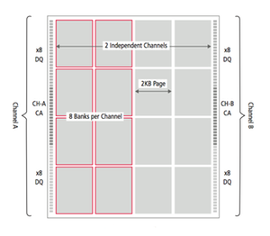
LPDDR4 is the latest standard from JEDEC, expected to be in mass production in 2014. The standard is optimized to meet increased DRAM bandwidth requirements for advanced mobile devices. LPDDR4 offers twice the bandwidth of LPDDR3 at similar power and cost points.
Figure 1 LPDDR4 architecture
To maintain power neutrality, a low-swing ground-terminated interface (LVSTL) with databus inversion has been proposed. Lower page size and multiple channels are other innovations used to limit power. For cost reduction, the standard LPDDRx core architecture and packaging technologies have been reused with selected changes such as a reduction of the command/address bus pin count.
Wide I/O 2: 2.5D and 3D integration for higher bandwidth
The Wide I/O 2 standard, also from JEDEC and expected to reach mass production in 2015, covers high-bandwidth 2.5D silicon interposer and 3D stacked die packaging for memory devices. Wide I/O 2 is designed for high-end mobile applications that require high bandwidth at the lowest possible power. This standard trades a significantly larger I/O pin count for a lower operating frequency. Stacking reduces interconnect length and capacitance, eliminating the need for ODT. The overall effect is to reduce I/O power while enabling higher bandwidth.
In the 2.5D-stacked configuration, two dies are flipped over and placed on top of an interposer. All of the wiring is on the interposer, making the approach less costly than 3D stacking but requiring more area. Heat dissipation is unlikely to be a concern with this configuration as cooling mechanisms can be placed on top of the two dies. This approach is also lower cost and more flexible than 3D stacking because faulty connections can be reworked.
EDA tools such as Cadence Encounter Digital Implementation help designers take advantage of redundancy at the logic level to minimize device failures. For example, it allows designers to route multiple redistribution layers (RDLs) into a microbump, or to use combination bumps. In this scenario, if one bump fails, the remaining bumps are still available to carry the signal.
With the 3D-stacked form of Wide I/O 2, heat dissipation can be an issue. There is not yet an easy way to cool the die in the middle of the stack, and that die can heat up the top and bottom dies. Poor thermal designs can limit the data rate of the IC. In addition, a connection problem – especially one occurring at the middle die – renders the entire stack useless, which can lead to yield and cost issues.
HMC: TSVs push bandwidth to 400GB/s
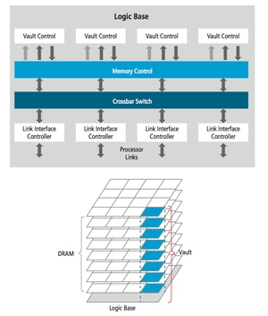
HMC is being developed by the Hybrid Memory Cube Consortium and is backed by several major technology companies, including Samsung, Micron, ARM, HP, Microsoft, Altera, and Xilinx. HMC is a 3D stack that places DRAMs on top of logic. This architecture, expected to be in mass production in 2014, essentially combines high-speed logic process technology with a stack of through-silicon-via (TSV) bonded memory die.
Figure 2 HMC architecture
In an example configuration, each DRAM die is divided into 16 cores and then stacked. The logic base is at the bottom, with 16 different logic segments, each segment controlling the four or eight DRAMs that sit on top. This type of memory architecture supports a very large number of I/O pins between the logic and DRAM cores, which deliver bandwidths as high as 400GB/s. According to the Hybrid Memory Cube Consortium, a single HMC can deliver more than 15x the performance of a DDR3 module and consume 70 per cent less energy per bit than DDR3.
HMC uses a packetized protocol on a low-power SerDes interconnect for I/O. Each cube can support up to four links and up to 16 lanes. With HMC, design engineers will encounter some challenges in serialized packet responses. When commands are issued, the memory cube may not process these commands in the order requested. Instead, the cube reorders commands to maximize DRAM performance. Host memory controllers thus need to account for command reordering. HMC provides the highest bandwidth of all the technologies considered in this article, but this performance does come at a higher price than other memory technologies.
HBM: An emerging standard for graphics
HBM is another emerging memory standard defined by the JEDEC organization. HBM was developed as a revolutionary upgrade for graphics applications. GDDR5 was defined to support 28GB/s (7Gb/s x32). Extending the GDDRx architecture to achieve a higher throughput while improving performance/watt was thought to be unlikely. Expected to be in mass production in 2015, the HBM standard uses stacked DRAM die, built using TSV technologies to support bandwidth from 128GB/s to 256GB/s. JEDEC’s HBM task force is now part of the JC-42.3 Subcommittee, which continues to work to define support for up to eight-high TSV stacks of memory on a 1,024-bit wide data interface.
According to JEDEC, the interface can be partitioned into eight independently addressable channels supporting an access granularity of 32byte per channel. There is no command reordering: instead the graphics controller is meant to optimize accesses to memory. The subcommittee expects to publish the standard in late 2013.
Which interface?
Each emerging memory standard tackles the power, performance, and area challenges in a different way. There are tradeoffs from one to another, with each optimized for a particular application or purpose. How do you select the right memory standard for your design?
Figure 3 Memory interface technology comparison chart
When considering a smartphone, for example, you may decide between Wide I/O 2 and LPDDR4. Because thermal characteristics are critical in smartphones, the industry consensus has turned to Wide I/O 2 as the best choice. Wide I/O 2 meets heat dissipation, power, bandwidth, and area requirements. However, it is more costly than LPDDR4, which is likely to be more suitable for cost-sensitive mobile markets.
On the other end of the application spectrum, consider high-end computer graphics processing, where chip complexity is a given and high-resolution results are expected. Here, you might look to the higher bandwidth HBM technology. Computer graphics applications are less constrained by cost than, say mobile devices, so the higher expense of HBM memory may be less of an issue.
Design support
To help integrate your design at the register-transfer level, EDA companies like Cadence offer IP portfolios for memory subsystems. Cadence has controller and PHY IP for a broad array of standards, including many of those discussed in this paper. Cadence also provides memory model verification IP (VIP) to verify memory interfaces and ensure design correctness.
Additionally, tools such as Cadence Interconnect Workbench allow the SoC designer to optimize the performance of memory subsystems through a choice of memory controller parameters such as interleaving, command queue depths, and number of ports. These tools can help speed up SoC development and ensure first-pass success.
Author
Gopal Raghavan, a Cadence fellow, is a well-known memory expert and is responsible for areas including IP roadmap development, SoC integration, and performance evaluation. He has electrical engineering degrees from the Indian Institute of Technology (bachelor’s) and from Stanford University (MS and PhD.).
Company info
2655 Seely Avenue
San Jose, CA 95134
(408) 943 1234
www.cadence.com


