The future of thermal simulation for electronics products
Complexity and the increasing use of thermal analysis software by non-expert designers demands new approaches for chip and PCB implementations.
Today’s electronics products are ever more tightly integrated. No longer can thermal design be separate from the mechanical and electrical design. It has to be front and center and considered from inception. Done well, this leads to far better products and lower cost cooling solutions. But it is critical that thermal design is properly incorporated in collaborative product creation processes.
Mechanical engineers are responsible for all aspects of the physical design—that is, everything beyond the electronics design, typically culminating in the PCB layout. They are responsible for the enclosure, the appropriate location of the PCBs and other components, and for ensuring structural integrity as well as safe, reliable operation. Cooling and thermal design is only one of their concerns, albeit an often crucial one.
Mechanical engineers collaborate with electronic designers using EDA software and with other mechanical designers using MCAD software. Thermal simulation and design software contributes to all stages of the design, from concept through exploration and optimization to final verification. These diverse needs have major implications for tool development, especially with regard to interfaces, data management, and integration.
Computational fluid dynamics (CFD)-based thermal simulation and design tools have traditionally been aimed at engineering analysts with specialist knowledge. These engineers still form core groups in electronics companies today. However, CFD-based thermal simulation users now also include electrical engineers, general mechanical design engineers, industrial designers, and marketing engineers.
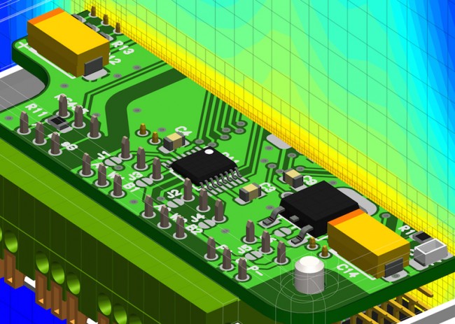
Electronics products are a complex assembly of many solid objects, including PCBs, electronics packages and devices, cabling, fans, and heatsinks. Air flow is confined within narrow regions between them (Figure 1). Convective transport within the air and conduction within the solid objects’complex internal structures is critical to temperature. Thermal simulation can involve thousands of such objects as well as extreme disparities in scale from meters to microns.
Fig 1 Thermal analyses must deal with extreme disparities in scale. (Mentor Graphics)
Because of the complexity, thermal simulation faces challenges in terms of geometry capture, scale disparity, uncertainty caused by missing data (for example, component thermal data, power dissipation, material properties, layer thicknesses, interface resistances), transitional flow regimes, mesh generation, the hardware environment, and high accuracy.
Thermal simulation challenges unique to electronics products
During detailed design, the geometry comes from both the EDA and MCAD design flows. EDA systems work with 2D representations because both IC and PCB design are done using schematics. PCB design tools require only the component layout and often do not contain even basic geometric information such as component height. Detailed information about the internal geometry of the chip packages is typically unavailable.
Miniaturization has created a disparity in length scales between the sizes of physical products and the sizes of their internal components and circuitry. Typically, meter-to-micron-scale geometry has to be accommodated within the same model. And the presence of small gaps can also effect cooling. Scale disparity continues to increase over time, which means that behavioral models are often required.
This raises another challenge: missing data. Material property data is absent from MCAD systems and this will affect CFD-based thermal simulation. Systems are constructed from many components from many suppliers, and the thermal characteristics are not provided nor well understood.
In cluttered electronic systems, air is forced through channels which contain all manner of protuberances. This induces a low Reynolds Number transitional flow. However, this wall-induced turbulence is not self-sustaining, and the flow will be laminar if the channel is smooth. Thus, turbulence modeling is also difficult.
Although generic to CFD, mesh generation for electronics cooling applications presents problems because of the sheer number of solid–fluid and solid–solid surfaces that must be captured. As a result, the meshing must be as automated as possible. It should require minimal intervention beyond the predefinition of mesh constraints on an object basis before meshing begins.
A fortuitous outcome of using EDA systems to design components and PCBs in 2D is that electronics have tended to contain large numbers of Cartesian-aligned objects. So Cartesian-based grid systems are the natural choice for this application. However, size constraints are forcing electronics designers to angle components on boards, insert DIMMs at an angle, and design heatsinks with non-Cartesian profiles.
Simple Cartesian meshes with grid lines that bleed out from an object to the edges are inadequate because they frequently result in unacceptable mesh counts when increasing geometric detail is added to the model. As a result, the use of locally refined Cartesian overset grids to optimize the mesh within and around objects has become prevalent. This allows either porosity or voxelization treatments to approximate non-Cartesian and non-aligned Cartesian objects with sufficient accuracy.
As the amount of non-Cartesian geometry present within systems has increased, so has the need for more sophisticated meshing. Over recent years, Octree meshes with MCAD-embedded CFD in early product design have increasingly been used where the product design process is built on a company’s MCAD system.
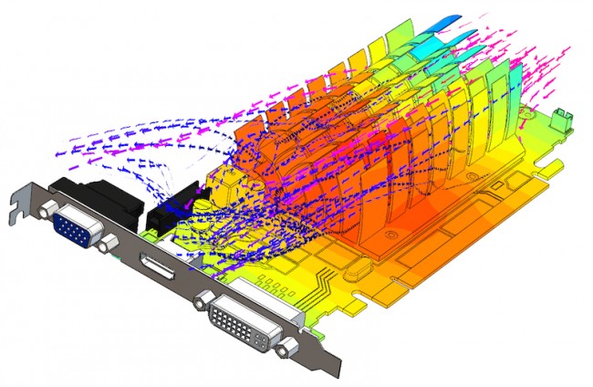
As design margins shrink, the need for thermal simulation accuracy increases. The allowable temperature rise from ambient to junction is not increasing, but as power densities increase within the package or PCB, the proportion of the temperature rise that occurs in the air is diminishing. Put another way, the importance of modeling the conduction within the solid structures is growing (Figure 2).
This explains the emphasis placed on MCAD and EDA integration to accurately capture the copper content and distribution on PCBs, effects such as Joule heating in traces, and power and ground planes. This approach can also accurately measure the thermal conductivity of TIM materials (particularly the softer Type I and Type II materials that are not well-suited to being measured with ASTM D5470–based equipment).
Fig 2 Modeling conduction within solid structures is increasingly important (Mentor Graphics.)
The state-of-the-art in thermal simulation
Thermal simulation results are used to judge design viability and commit significant development resources in an environment where delays of just a few weeks can lead to a missed market window.
The cycle from concept to first shipment can be as short as nine months. Delays of even a few weeks can severely affect profits. Electronics cooling design and thermal simulation applications have to be quick, reliable, and integrated into fast-moving, complex design processes.
Mentor Graphics’ latest thermal simulation software for electronics products, FloTHERM XT, provides an environment in which geometry can be changed and the simulation results rapidly regenerated. It is designed to fit into complex mechanical design environments and associated processes that exist today. Imported CAD and internally generated geometry function seamlessly together, thus enabling supply-chain integration and offering an opportunity for the tool to fit anywhere in the mechanical design flow.
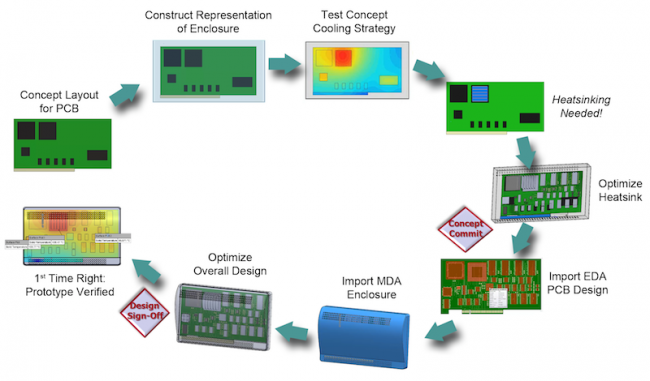
The FloTHERM thermal simulation tool minimizes the risks associated with the thermal aspects of the design as early as possible. By incorporating a solid modeling engine and native links to EDA design suites, companies can bring the mechanical and electrical design disciplines closer together through the creation of a 3D model of the product that can be as simple or detailed as necessary, and in sync with the design in the MCAD and EDA systems (Figure 3).
Fig 3 Thermal simulation must fit into complex mechanical design environments and associated processes (Mentor Graphics.)
By allowing users to start thermal simulation at the conceptual stage and retain data consistency and history as the design evolves, FloTHERM reduces design iterations to correct late in-process errors and cuts time-to-market.
The tool was developed in the recognition that various types of personnel carry out thermal simulation and analysis. It is designed for use by design engineers as well as thermal specialists. As a result, ‘what-if’-studies and experimental or innovative design changes can be quickly assessed, without overburdening thermal experts.
The tool can also bridge the gap between EDA and MCAD design flows. It is directly integrated with Mentor Graphics’ PCB system design tools and includes automatic updating, which is less error-prone and time-consuming when working with board designs generally or with subsequent updates as the board design evolves.
This design flow using FloTHERM XT also provides filtering capabilities for thermally irrelevant devices and supports automatic connectivity to thermal model package libraries. It uses intuitive object-based meshing and a customizable interface as well as model building controls. This results in a significant reduction in simulation time.
Conclusion
Design complexity is driving EDA and MCAD design flows closer together, putting pressure on thermal designers to use native geometry from these systems without simplification to keep the simulation model up to date, minimize the time taken to analyze design variants, and increase accuracy of results.
These changes have affected the demands placed on engineers, with implications for software usability, geometry handling, and underlying CFD technology. Thermal simulation software that supports different types of design engineers and levels of expertise is needed as much in early design as it is in late stage verification.
About the author
Dr. Clark has been heavily involved in computational fluid dynamics (CFD) and electronics cooling since the mid-1980s. He started his career at CHAM and moved to Mott MacDonald as a member of the CFD development team. He then joined Flomerics (now Mentor Graphics) in 1991. Dr. Clark currently is a Product Manager for the Mentor Graphics Mechanical Analysis Division, and he is responsible for new electronics cooling product development. He received his MSc in Meteorology from Edinburgh University and PhD in Marine Science from Plymouth University.


