FMEA in automotive software development using virtual prototyping, physical modeling and simulation
How fault mode and effect analysis (FMEA) can be performed on a virtual prototype of an automotive system containing mechanical, electrical, analog and digital models, including the microcontroller running the same software as will be used in the car.
Automotive safety-critical systems are now so complex that it is no longer possible to develop and test their parts in isolation and expect smooth integration. Mechanical, electrical, electronic and software components need to be brought together as soon as possible to validate system behaviour. One reason for this is the increasing complexity of functional features, diagnostics and recovery mechanisms implemented as a combination of embedded software and electronic hardware.
Validating a safety-critical system requires developers to prove that it will work under the expected operational conditions and can also recover (within a time limit) from any fault in the system. This is practically impossible on conventional hardware prototypes or with in-the-loop methods.
Functional safety processes
The functional safety of a system depends on it working correctly in response to its inputs, including the safe management of likely operator errors, hardware failures and environmental changes. Any assessment of functional safety must examine the function of any component or subsystem in the context of the behaviour of the whole system.
The ISO 26262 standard
ISO 26262 is a functional safety standard for passenger vehicles that addresses hazards caused by malfunctioning electric and electronic safety systems. It focuses on the electrical/electronic programmable systems (EEPS), and requires assurance that functional safety extends to parts of the system that the EEPS activates, controls or monitors. The standard provides:
- An automotive-specific safety lifecycle of three phases: concept, product-development and post-production.
- An automotive-specific risk-based approach based on Automotive Safety Integrity Levels (or ASIL), which are defined in terms of severity, exposure, and controllability. ASIL D is the highest safety integrity level and ASIL A the lowest.
- Requirements and recommended methods for the validation of the safety levels, for the software, hardware and system.
[There’s more on the ISO 26262 and ASIL in this related piece.]
System-level reference models
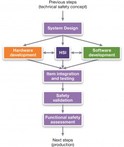
Part 4 of ISO 26262 defines a reference model (Figure 1) for system-level product development that involves both hardware and software. It starts by specifying the technical safety requirements, including the safety mechanism, from which the technical safety concept is derived. The technical safety concept and the system-design phase describe how the functional and safety requirements will be implemented. Single-point and multiple-point fault scenarios are analyzed and aspects such as fault-tolerant time interval, detection time, and fault reaction time, are described.
Figure 1 ISO 26262’s reference model for system-level (Source: Synopsys)
Safety analysis of the system is performed using both deductive methods such as fault tree analysis (FTA) and inductive methods such as fault mode and effect analysis (FMEA).
Another important part of this approach is the hardware/software interface (HSI) specification, which describes how hardware and software should interact according to the technical safety concept. This includes the hardware that runs the embedded software, and all the hardware it controls.
The reference model also defines integration, testing and validation at different levels: hardware/ software, system and vehicle. Different methods can be used to perform the validation, including simulation and prototyping methods. For software integration and testing, ISO 26262 recommends using both fault-injection testing and structural-coverage metrics for ASIL levels C and D.
The limitations of conventional fault methodologies
Fault injection helps to determine whether the response of a system matches its specification, despite the presence of faults. Hardware faults can be categorized by their duration as: permanent faults (triggered by component damage), transient faults (triggered by environmental conditions, also known as soft errors), and intermittent faults (triggered by unstable hardware). Software faults are the result of an incorrect design either at the time of specification or coding.
Existing fault methodologies are cumbersome, time-consuming, and difficult to use in a way that gives repeatable results. Most problems are due to using physical hardware prototypes to perform the experiments, since hardware prototypes lack flexibility, controllability and determinism.
Hardware-based fault injection is done at the physical level, for example by changing the value of the pins of an Electronic Control Unit (ECU) or by disturbing the hardware with electromagnetic interference or heavy ion radiation.
Software-based fault injection aims to reproduce errors introduced by hardware faults without modifying the hardware, but can only inject errors in places the software can reach, such as memory and registers for memory-mapped peripherals. The biggest problem with software-based fault injection is that it involves changing the software by inserting code to cause errors, which means it my act differently to the production software.
Traditional simulation-based fault injection has full access to all hardware elements in the system, offers full observability and controllability, and is fully deterministic. But it is slow, and therefore unusable for more complex fault scenarios where software must be taken into account.
‘Virtual FMEA’ can help address these issues.
Virtual FMEA
What does a ‘better’ approach to simulation-based fault injection look like?: It should:
- Provide full access to hardware injection points, both within the ECU and at its I/O signals
- Not intrude on hardware and software behavior
- Be fully repeatable and automated
- Be fast enough to execute complex scenarios
- Integrate into an ISO 26262 process
Our simulation-based fault methodology relies on three main concepts:
- Virtual prototyping of the physical system as an execution platform – also known as ‘virtual Hardware-in-the-Loop’ (vHIL)
- Links to FMEA by providing tool support to define faults (e.g. injection point, fault type, duration, etc.) and scenarios (e.g. when faults are inserted, plus other system stimuli).
- Automated generation of fault reports and the measured effects on the system
Virtual Hardware-in-the-Loop
Modeling heterogeneous automotive systems made up of mechanical, electrical, analog and digital electronics, and embedded software is a challenge.
One way to do this would be to have a tool or modeling language that tries to address all paradigms at once (physical, electrical, digital, analog, software, etc.), although this is unlikely to work because of its complexity and a lack of supporting models.
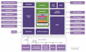
A more proven likely approach links the best tools for each domain to each other through co-simulation, as shown in Figure 2.
Figure 2 vHIL concept based on co-simulation (Source: Synopsys)
Physical and electrical parts can be simulated in a tool such as SaberRD, which is already used in the automotive industry and so makes access to the relevant models much easier. The MCU running the binary software in the ECU can be simulated using a Virtualizer Development Kit, a virtual hardware model which mimics a microcontroller well enough to run the same software as used on the real hardware. The rest of the network can be simulated in a tool such as Vector CANoe, so that the software can be provided with the same CAN bus stimuli without the need to simulate the whole subsystem as the same level of detail.
All these tools connect with each other using our Virtualizer System Interface (VSI) to exchange data and synchronize the simulated time.
FMEA support
For the vHIL environment to be useful for FMEA, we need to know which types of failure to look for.
We could look for various types of faults such as:
- Connection faults, includes shorts and open circuit, and other types of connection faults in the mechanical, hydraulic, pneumatic, magnetic, logical etc., domains
- Variation faults, due to one attribute of the design changing from a nominal value caused by e.g. thermal drift, aging, or production tolerances
- Logic faults, such as ADC or DAC conversion errors, or digital logic errors
We could also consider temporal aspects, such as:
- When the fault is injected
- When the fault ends – if it does
And we could consider combinations, when more than one fault happens at once – especially to understand the behavior in corner cases.
A useful FMEA approach needs to derive and configure extremely large numbers of single and combinatorial faults in an efficient manner.
Defining experiments
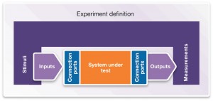
Once the fault set for the system has been decided, the conditions under which those faults should be applied also need to be specified – effectively defining the experiment to be performed. The experiment definition needs to contain: acceptance criteria (pass/fail); stimuli to the system; inputs and outputs of the system of interest; connection points where the system is linked with stimuli and/or measurements; as definitions of the measurements to be taken (see Figure 3).
Figure 3 Setting up a vHIL experiment (Source: Synopsys)
An experiment set up this way could be run many times, with different combinations of faults, to validate the Technical Safety Concept defined in ISO 26262.
Analysis and reporting
The next step is to run the experiment and analyze the results, using a report generated by the virtual prototyping tools. This provides a quick overview of experiment results, with pass/fail metrics for the key criteria and measured values for different fault conditions. A tabular report can be exported as an Excel sheet for reporting purposes. The tool also generates graphs of waveforms, which can be used directly for analysis or exported for use in documentation.
This experimental flow can help identify critical faults within a system and allow for further analysis and simulation on the conditions that most affect the functional safety of the design. Once the flow is established and the appropriate experiments and fault sets defined, along with any additional analysis steps on the results, the whole process can be further automated through scripting, which enables a scalable, reliable, repeatable and automated testing platform.
Conclusion
Virtual FMEA uses virtual hardware models as the underlying execution platform. It enables users to define faults and scenarios in which they happen, and then simulate them repeatedly to see what happens. Fault reports. defining the impact of a fault or set of faults on a system under various scenarios, are generated automatically. The combination of these three features enables users to respond effectively to the demands of implementing the system-level reference model of an ISO 26262 approach to functional safety.
Further information
The second part of this whitepaper will apply these concepts in a case study, where an electrical drive system is refined to a vHIL model. Hardware faults are applied to the system and its response at both the hardware and software levels are analyzed using our virtual FMEA solution.
There’s a related piece on this topic here.
Authors
Victor Reyes is technical marketing manager, virtual prototyping group, Synopsys. Kurt Mueller is business development and CAE manager, Asia-Pacific region, Saber, Synopsys.


