When failure is not an option in automotive verification
The ISO 26262 safety standard lays out a number of best practices for the automotive industry and for suppliers. Formal verification provides a way of streamlining the verification of SoCs that need to conform to the standard.
The failure of a safety-critical device, such as an automotive chip that affects a car’s operation, has an impact far greater than just financial. However, the increasing functionality and integration density of these devices make random and systematic failures more likely than in previous generations. Problems with automotive safety-critical circuits are visible in the market, driving customers to demand specific and rigorous safety measures.
Component vendors have had to take an active role to ensure system safety by design, which now includes developing and verifying devices to the ISO 26262 automotive safety standard that is now being adopted by car manufacturers. The standard provides best practices for the automotive industry, driving automated processes to avoid systematic failures through human and design flow errors, and providing a basis for safeguarding systems against random failures. The exhaustive nature of formal verification technology makes its application a natural choice for the verification of devices designed for the ISO 26262 regime.
Vehicle safety has come a long way since the advent of air bags and improved mechanical systems, and part of the reason for this is the significant growth in automotive electronics. Modern cars have hundreds of processors involved in every facet of operation.

Image Electronics hardware is helping ADAS rapidly evolve for automotive applications (Image: Xilinx)
Although this revolution has improved safety, there are always issues with the use of highly complex devices. Spotlighting the problem are cases of unintended sudden acceleration or the recent GM recall for cars that could turn themselves off while cruising at speed. Often the root cause of these issues is never identified with certainty, focusing the accusatory spotlight on design methods. ISO 26262 defines guidelines, best practices and hazard levels to achieve functional safety of electronic systems. It is inevitable that chip makers supplying the automotive industry will be forced to comply with the standard in order to sell their products.
Failure types and ISO 26262 requirements
There are two basic failure types that must be addressed. Systematic failures are introduced during the design process through human error or methodology issues and affect all parts of a product series. Examples include synthesis bugs, simple programming errors, implementation to specification mismatches, and even specification errors. Proper verification practices reduce these errors and the use of formal verification by automotive chip vendors has become commonplace due to the exhaustive nature of the technology. Formal verification technology is the basis for a number of tools that provide rigorous test and measurement solutions.
Random failures, on the other hand, are introduced by field conditions and, as such, are harder to eliminate. An example is a bit-flip in a chip memory caused by a minor electromagnetic event. As there is no way to completely rule out such events, their affect must be minimized by design. The highest safety standard, or Automotive Safety Integrity Level (ASIL) defined in ISO 26262 is level D. This sets the likelihood of malfunction to a statistically defined failure rate of 10−9 per hour, or one in every 114,155 years. To achieve this, the system must be designed to be fault tolerant. Two fault-tolerant design methods commonly leveraged are component redundancy and active failure management.
For the most critical ASIL D parts of the system, several layers of safeguarding mechanisms are deployed. The lower layer consists of techniques including error-correcting codes used to catch memory errors, and triple-modular redundancy that compares the output of a component against two equivalents to trap an error in any of them. At the next layer, failures are reported to a safety-management unit that keeps track of failure numbers and reports them to a higher layer implemented in software. This safety-management software can react to these events by actively employing safeguarding procedures, such as re-initializing some hardware components. This happens in real time without disrupting the safety-critical functions while the car is in motion.
The safety-critical verification challenge
The verification of such safety mechanisms poses a number of challenges. First, the number of potential failure locations is huge, corresponding to the number of flip-flops in the design. Considering different failure types, such as stuck-at faults, short circuits, transient faults or occasional bit flips, and combinations thereof, as well as the potential for multiple faults at different locations, the number of operational scenarios to test is astronomical.
The second challenge is the effective modeling of these failures to observe the proper reaction of the system. For example, how do designers tell the simulator to sometimes flip a bit in some of the redundant flops without changing the circuit?
Third, where is the verification procedure targeted? Synthesis tools are clever at finding and eliminating design redundancies, including those included deliberately. So, pre-synthesis register transfer level (RTL) verification is not always a good choice. For this reason, ISO 26262 requires the demonstration of the proper function of safety mechanisms at the final gate level, including any software. It represents a verification performance black hole.
Finally, how do designers prove they have properly tested all relevant failure locations for all relevant safety functions? They have to measure verification coverage. However, just ensuring that all the lines of code have been stimulated is not enough. Coverage metrics based upon the question, “if there is a bug in the design, will it be spotted during verification?” must be employed and this requires observation coverage.
To illustrate safety-critical design verification in action, let’s consider a number of examples and discuss how these are handled today in real design scenarios. We will look at the verification of designs using error correction codes, redundant systems, and overall test qualification.
Safeguarding memory
Keeping track of sensor data, such as acceleration over time to recognize hazardous conditions for airbag release, requires the storage of data in memory. If this data is corrupted due to random failures, the malfunction of a safety measure may result. To prevent this scenario, memories are often equipped with error correcting codes.
Data is encoded when stored in the memory and decoded when read, using a code designed to recognize and repair any errors in one or more bits. The type of error correcting code determines how many random failures can be caught and corrected. When verifying error code correcting (ECC) memories using simulation, it is hard to anticipate all relevant error conditions making the solution inefficient for large data sets.
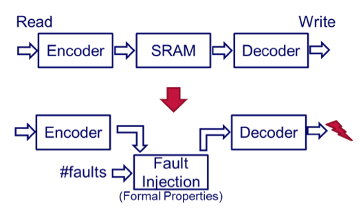
Figure 1 Testing ECC RAM using formal fault injection (Source: OneSpin)
When using formal techniques, the basic idea is to overlay the memory with a set of formal properties that specifies code behavior and injects faults as required. Utilizing fault injection, the verification task becomes one of proving that the test mode operates correctly, and then that a given number of injected errors will be properly corrected.
Using formal verification, the type of errors is immaterial. The number of errors can be parameterized in the property set. This way, a huge number of combinations of potential faults can be handled, a high number of parameter and inputs are covered, and no knowledge of the ECC algorithm is required.
Safeguarding data using redundancy
A similar problem arises for status and control registers. Here, data coherency is protected by duplicating or even triplicating each register flop and comparing outputs to ensure that all flops match. Safeguarding logic detects mismatching values, and can potentially correct the output value, as well as raise an alarm within the safety management unit.
Similar to the memory case, the verification problem is to prove that an alarm generation works in test mode as well as in normal mode with error injection. It also needs to ensure any detectable error is flagged while no false alarms are raised.
In addition, it is necessary to prove that all individual sources for alarms are properly propagated to the safety-management unit, and handled correctly. As well, it is necessary to prove that no functional side effects are added by the safeguarding logic and that the error correction allows normal operation to proceed. With simulation, typically only a limited number of faults can be tested, often with a low degree of automation and incurring long simulation times.
Using formal property checking, it is possible to exhaustively activate all potential faults, including multiple faults. Again, using formal properties to describe the fault scenarios, a high degree of automation is achieved while large blocks and huge numbers of faults can be handled simultaneously. This leads to a reduction in verification setup and run time from weeks and days, to hours and minutes.
Qualification of the verification environment
In order to qualify a verification environment in context of ISO 26262, it is necessary to prove that the safety-critical aspects of the design are properly verified. Observation coverage is the method of choice when looking at formal verification environments.
Traditional simulation coverage in general is designed to ensure that simulation stimulus actually reaches all the code in the design. However, it does not ensure that verification checks will pick up a fault in a particular line. Any environment with inadequate checks may not find a bug if it exists, regardless of how good the stimulus is.
Formal-based observation coverage uses a system that temporarily replaces code segments with a “free variable” that the formal engine interprets as an alternative state. If an assertion detects the alternative state, then the coverage of that segment is assured. If the segment behaves unexpectedly, the environment will detect this issue. This leads to a more precise coverage metric as well as clear guidance as to whether additional assertions are required.
Summary
Formal verification can improve verification quality and productivity in the context of compliance to ISO 26262. A broad range of formal verification solutions can target the design structures necessary to deal with typical aspects of systematic and random failures inherent in automotive designs far more effectively than simulation-based systems. The quality of verification is improved, as well as the time taken to achieve this result, leading to safer and more reliable vehicles.
About the author
Dr Raik Brinkmann, a co-founder of OneSpin Solutions, was named president and CEO in 2012, with overall responsibility for leading the company and its business growth worldwide. He brings to this role more than 15 years of broad expertise in management, verification and industrial R&D, having served at companies in both Europe and the US. He holds a Diplom Informatiker from the Clausthal Technical University, Germany and a Dr-Ing from the Department of Electrical Engineering at the University of Kaiserslautern, Germany