Improving functional safety of automotive systems using virtual prototyping
The increasing complexity of automative software is challenging the ability of established software testing strategies to demonstrate its functional safety. Here’s how virtual prototyping can help.
The automotive industry faces a particular challenge in balancing product safety with time to market. Although the auto industry has been very successful in increasing vehicle safety, helping to reduce the number of fatal auto accidents in the US by almost 25% between 2005 and 2009, it has been at the cost of much greater hardware and software complexity.
A modern automobile may rely on 100 million lines of code, five times as many as used in an F35 fighter jet. Software now makes up 13% of the overall development effort for a new vehicle, with ECU diagnostics accounting for 40% of the code and processor runtime, and 25% of overall test costs.
Even as the amount of code used in autos is increasing, so are the demands of safety regulations. Something has to change to ensure that an increasing amount of code can be verified in an increasingly complex electrical, electronic and electromechanical context, to increasingly rigorous standards, in the same amount of time – or less.
Accelerating software test through better simulation
Automotive manufacturers need to shift software testing ‘left’ in the development process, so that developers don’t have to wait for a physical prototype to be built before they can start work. Some are already on this path, working with hardware subsystems in the testing loop before a complete prototype is built, or using simulation models of the hardware to start work on software testing and integration even earlier in the development process.
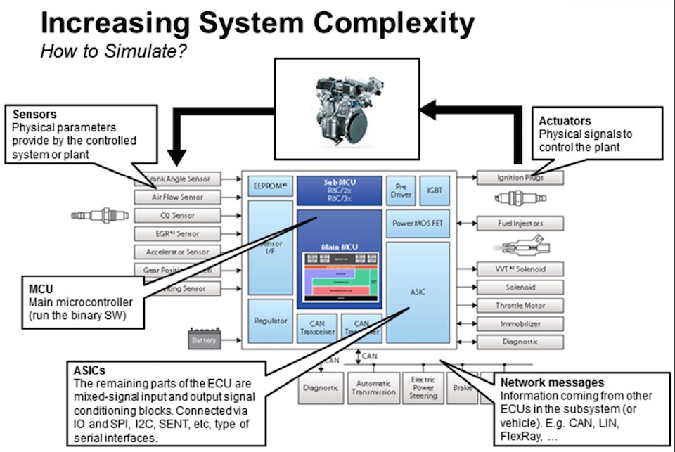
Figure 1 The complex challenge of simulating an automotive system (Source: Synopsys)
What’s the right way to simulate such systems? The answer is probably not look for one tool that can simulate everything at once, but to use targeted tools for specific parts of the job. Synopsys’ Saber tool, for example, can handle mixed-domain simulations of electromechanical systems, while Synopsys Virtualizer Development kits can be used to simulate digital hardware such as automotive microcontrollers. The automotive network can be simulated in a dedicated tool such as CANoe.
Functional safety
Better simulation strategies can accelerate software testing and integration, helping to shrink development times. Unfortunately for auto makers, increasingly stringent safety requirements are making testing more complex, expanding development times again.
What’s the core challenge of functional safety? Part of the overall safety of a system depends on the system operating correctly in response to its inputs, including the safe management of operator errors, hardware failures and environmental changes. The objective is freedom from unacceptable risk of physical injury or damage to the health of people, directly or indirectly. Meeting this objective is an end to end issue that has to consider the whole system and its environment.
ISO 26262 is a functional safety standard for passenger vehicles, which address hazards caused by malfunctioning behaviour of electrical and electronic safety-related systems. The standard provides an automotive safety lifecycle, an automotive-specific risk-based approach with automotive safety integrity levels (ASIL), and requirements for validation of safety levels.
It isn’t mandatory to meet the standard, but it is best practice, and automotive manufacturers who don’t use it may open themselves to legal liabilities in the event of an accident involving one of their vehicles.
Figure 2 Three phases of system development as defined under ISO 26262 (Source: Synopsys)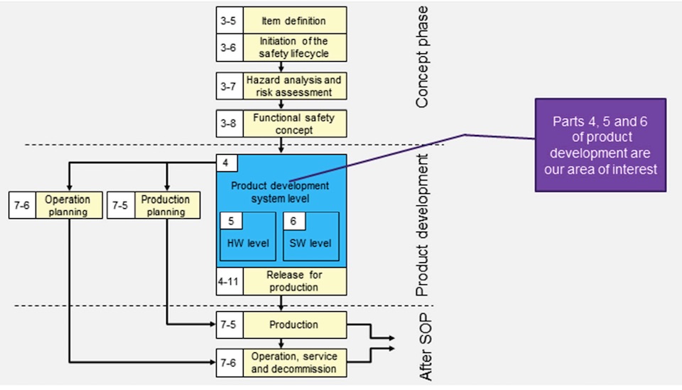
ISO 26262 suggests three phases of the development process.
The first is the concept development phase, in which you define what you’re building in terms of its functionality, interfaces, environmental conditions and a hazard analysis that defines its automotive safety integrity level (ASIL). Using the safety goals developed from this analysis, you can then develop a functional safety concept.
The second phase is product development, during which you develop your product using a typical V model of hardware and software development, with separate flows for each.
The third phase is after start of production, when you consider issues such as operation, servicing and decommissioning.
Automotive safety integrity levels
Three aspects define ASIL: severity, exposure and controllability.
Severity is graded as follows:
- S1 – light to moderate injuries
- S2 – severe and life threatening injuries (survival probable)
- S3 – life threatening and fatal injuries (survival uncertain)
Exposure as follows:
- E1 – very low probability
- E2 – low probability
- E3 – medium probability
- E4 – high probability
And controllability as follows:
- C1 – simply controllable
- C2 – normally controllable
- C3 – difficult to control or uncontrollable
Figure 3 ASIL levels depend on a combined assessment of risk severity, exposure and controllability (Source: Synopsys)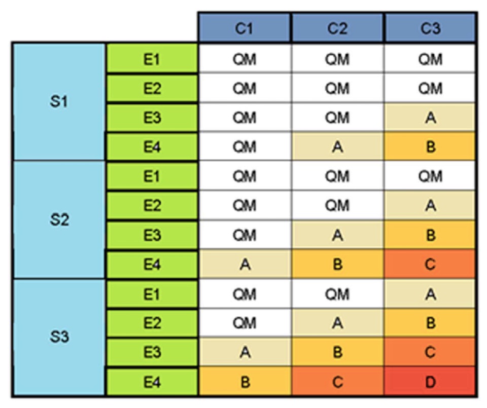
As the table shows, different combinations of severity, exposure and controllability lead to different ASILs, with ASIL A being the lowest safety integrity level and ASIL D the highest. The table shows that for some combinations of severity, exposure and controllability, there’s no requirement for quality management under ISO 26262.
Part four of ISO 26262 also provides a reference model for system level design, which says that developers need to do both a deductive ‘failure tree analysis’ (FTA) and an inductive ‘fault mode and effects’ (FMEA) analysis for systems specified to ASIL levels C and D.
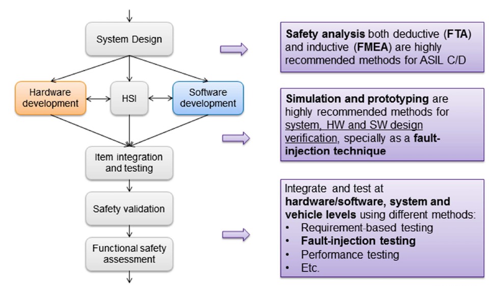
Figure 4 The ISO26262 reference model for systems design (Source: Synopsys)
The standard also recommends using simulation and prototyping for system, hardware and software design verification. Approaches that may be relevant to the process include requirements-based testing, fault injection, performance testing, and so on.
A better fault testing methodology
Fault testing is often done today by taking a physical system, injecting faults into it physically. Measuring what happens and then writing a fault report and passing it to a product life-cycle management or requirements tracking system. This is expensive, slow, and prone to errors, for example in terms of the consistency between repeated measurements.
In a simulation-based approach, we develop a virtual model of a physical system (in a tool such as Saber), and then apply faults and measure the system’s response – without having to set up a testbench or potentially destroy a prototype. Once the simulation has been run, the tool can automatically generate a report as well as simulation models and a simulation testbench, which can be passed to the product life-cycle management and requirements tracking systems.
The aim of this work is to understand system complexity and fault propagation through analysis. We need to be able to look at failures at the vehicle level, the ECU level and the chip level, and understand what happens to the vehicle if a chip or ECU fails.
FTA vs FMEA
Fault analysis and verification means considering systemic hardware failures, such as hardware bugs, random hardware failures, systemic software failures – and failures in the interaction between hardware and software. We want to be able, for example, to see what happens if we get a false signal in the hardware and it is propagated into the software, or to see what happens if a signal-processing algorithm misbehaves and affects the hardware. To do this you have to be able to look at all the different levels of the design at once in the same environment.
There are two ways of thinking about this challenge: FTA (fault tree analysis) and FMEA (fault mode and effects analysis).
FTA is a top-down methodology in which we define undesirable behaviours at the top level and then work out what could cause these behaviours. We then assign probabilities to each of these types of failure, and use combinatory logic to assess the likelihood and impact of different combinations of failures. Using ‘Hardware-in-the-Loop’ techniques, we can validate the assumptions made in the analysis by inserting the different faults into the fault tree to see what happens.
FMEA, on the other hand, is a bottom-up methodology in which you identify possible failures and then determine the effect of the failure mode and how the failure can propagate.
Tools such as Synopsys’ Saber RD Fault solution enable users to automate fault simulation and results reporting to support your approach to fault analysis.
As yet there are no standards for tracking safety requirements, or standard tools to do so. Our customers are using various approaches, including: as part of product life-cycle management and requirements tracking schemes; FMEA approaches; FTA approaches; and thorough test coverage.
Our goal is to develop ways to link to whatever solutions our customers are using, so that their FTA or FMEA flows are automatically linked to their product lifecycle management and requirements tracking tools.
This is something we can already do, in part, under Saber, with automated experiments, closely tied to fault analysis, with at a glance pass/fail reports, and traceable documentation.
Conclusion
Automobiles are getting safer, in part because of the introduction of advanced driver assistance features such as lane keeping. While this is good news for passengers and non-passengers alike, it has greatly increased the software development burden for automotive companies. For these companies to produce new models and meet increasingly strident safety requirements, development methodologies have to evolve. Greater use of simulation in hardware and software development, and more sophisticated analysis of faults and their implications should ensure that vehicles keep getting safer.
Further information
To learn more about functional safety for automotive system development, please visit: https://event.webcasts.com/starthere.jsp?ei=1057083
Author
Victor Reyes is technical marketing manager, virtual prototyping group, Synopsys. Kurt Mueller is business development and CAE manager, Asia-Pacific region, Saber, Synopsys.
Company info
Synopsys Corporate Headquarters 690 East Middlefield Road Mountain View, CA 94043 (650) 584-5000 (800) 541-7737 www.synopsys.comSign up for more
If this was useful to you, why not make sure you’re getting our regular digests of Tech Design Forum’s technical content? Register and receive our newsletter free.