Spot the difference between false and real clock violations
Find how to spot some of the most common false clock-domain crossing (CDC) violations and how to efficiently find actual CDC problems that could kill a design if not corrected.
Clock domain crossings (CDCs) are a major source of complex SoC design errors that can and do easily slip past conventional verification tools and make their way into silicon. Thus it is essential to spot the real clock domain violations quickly in the design process. However, just as important is the verification engineer’s ability to root out false violations.
Unfortunately, cycle-based simulation, the mainstay of RTL-stage verification, is not well suited to finding and tracing timing-related errors resulting from CDC problems. While traditional structural analysis tools can help identify potential problem areas, none offers the kind of comprehensiveness or precision users require.
Why is this important? When these errors make it into silicon, we have to contend with – and explain to our managers – why the project has incurred silicon re-spins that may cost $10m and extend time-to-market by months, thus greatly reducing the chip’s market share and profit potential. Even if caught prior to silicon, in the late stages of design, a single bug may still run up $100,000 or more in redesign costs, which is unacceptable to the project manager and the customer.
There are several major classes of false violations, and a variety of approaches are needed to exclude them from the final violation report. One major class is that of mode-dependent CDCs.
Common false positives
Some conventional tools lack the ability to analyze operational modes such as test mode and other functional modes that enable identification of relevant clock domains. As a result, conventional tools often mistakenly identify crossings between clock domains that are not true crossings, thus adding numerous false violations into the reports. To address this problem, tools should provide methods such as case-analysis to automatically find and exclude such false crossings from violation reports. Common mode-dependent CDC situations include:
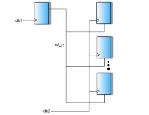
1) Quasi-static signals. Certain signals – such as reset and other configuration signals – are quasi-static. That is, they are effectively stable for long periods of time. Such crossings do not require synchronizers in the destination domain, because they are held long enough to be captured by even the slowest clock domains without the risk of metastability. Traditional tools that indiscriminately define all unsynchronized crossings as CDC violations report a number of false violations based on such quasi-static signals. New tools should therefore provide a way of screening such signals from consideration. For example, users could specify which signals and paths the tool should disregard when searching for CDC violations.
Figure 1 An example of a quasi-static signal
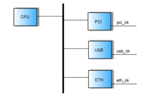
2) False paths: This is another large category of crossings that don’t require synchronization. False paths are apparent crossings, detected by structural analysis, that are never activated. Take, for example, a bus driven with a CPU master and multiple IO interface slaves – PCI, USB, and so on. The bus arbiter is designed so that a slave can communicate with the CPU and vice-versa, but a slave cannot communicate directly with a slave. Yet CDC analysis is likely to show domain crossings between usb_ck and pci_ck and so on. Here again, users should be given the ability to point out such paths and direct the tool to exclude them from the violation list.
Figure 2 An example of a CDC false path
3) Memory cores in FIFO synchronisers: Another group of signals that do not require synchronization when crossing domains are those that read from the memory core in a FIFO synchroniser (that is, FIFOs used specifically for synchronization). Because of the latency between writing to and reading from any given location in the core, such signals are, for all intents and purposes, quasi-static and should be excluded from violation reports. Tools should ideally recognize such cores and omit them, or at minimum allow users to waive analysis in these cases.
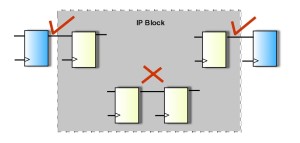
3) Custom synchronisers: Tools may detect commonly used synchronization structures, such as two-flop or multi-flop synchronizers. But traditional tools may fail to recognize a variety of other approaches–including custom, user-designed synchronizers. Therefore, in addition to having a large pre-defined library of standard synchronization structures, tools should allow users to specify any custom synch structures used in their design. When doing its structural analysis, the tool will then recognize these user-defined elements as valid synchronizers and not mistakenly report such crossings as unsynchronized.
Figure 3 Handling of IP blocks in CDC verification
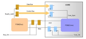
4) Handshake mechanisms: Handshake protocols – which coordinate transmission between the source and destination domains – are another popular synchronization technique, but one that traditional structural analysis tools often fail to recognize. New tools are therefore needed with advanced structural analysis capable of recognizing a wide variety of handshake mechanisms. As detailed in the next section, tools can be of even greater value if they are also able to functionally verify handshake mechanisms.
Figure 4 Handshaking synchronization is a commonly used technique that can result in numerous false violations
As we can see, there is an excess of conditions and circumstances that easily lead to false violations due to insufficient tools, verification techniques and simple SoC design complexity. Working hand in hand with our need to sidestep false violations, it is necessary to uncover and fix actual CDC errors, which is a lot like avoiding stepping on land mines while trying to clear a mine field filled of those land mines. It’s a tough job.
Detecting problems at synchronized crossings
Simply synchronizing a signal does not necessarily address all potential CDC problems. There are a number of important errors that can occur at synchronized crossings, and CDC verification tools should be able to detect the following violations:
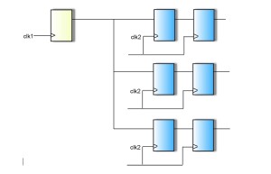
1) Cross-domain fan outs: These are signals transmitted from one flip-flop in the source domain to multiple flop synchronizers in the destination domain. This may result in loss of signal correlation, and is therefore a bad design practice that CDC tools should flag. The correct method for handling this case is to synchronize the signal only in one place, then to fanout the signal after synchronization.
Figure 5 Fanouts into multiple clock domains
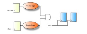
2) Cross-domain fan ins: A cross-domain fanin occurs when two signals originating from separate source domains are combined through combinational logic in the destination domain. This scheme is glitch-prone since there is no fixed phase-relationship between the incoming signals. The correct method to handle this case is to synchronize the signals separately before combining them in common logic. Again, tools should be able to detect and report this class of violation.
Figure 5 Fanouts into multiple clock domains
3) Reconvergence: Yet another design practice that can result in functional errors is reconvergence, where two or more signals from different domains converge on combinational logic after synchronization. Once again, loss of data correlation may result. Tools should automatically detect and flag these violations.
Figure 6 Fanins of multiple signals crossing clock domains can cause glitches
4) Handshake violations: As described above, handshaking is a common method of synchronizing signals across domains, and tools should have the ability to recognize handshake structures. Beyond these structural capabilities, new tools can be of great benefit if they also include the ability to functionally verify the handshake (REQ-ACK) protocols. This latter, functional analysis requires assertion-based verification, preferably in the form of automatic, or implicit, checks.
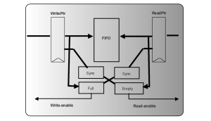
5) Gray code violations: When control buses cross clock domains, there is a danger that slight differences in propagation among the bus wires will cause loss of correlation in multi-bit data. To prevent this, Gray coding must be used to ensure that only one bit on a multi-bit bus changes on any given clock cycle. CDC tools should therefore verify correct implementation of Gray codes on all buses that cross clock domains. As with handshake protocol checking, this requires formal, assertion-based analysis. It should be done automatically, using implicit checks.
Figure 7 FIFOs are a good example where read and write pointers need gray-code encryption
6) Hold time violations: In cases where a signal crosses from a faster clock domain to a slower one, a pulse extender can be used to hold the signal to meet the capture time of the destination domain. CDC tools should therefore be able to, one, recognize fast-to-slow crossings and, two, apply assertion-based analysis to verify that signal hold times are adequate. All of this should be done automatically, with no need for user intervention.
Figure 8 When signals cross from a fast to a slow clock domain, hold violations can result
Required tool capabilities
It is apparent that we need analysis and verification tool technology that will help us detect CDC errors and avoid designating false violations. In addition, tools should be able to handle any size design, up to and including those with tens of millions of gates. Mixed-language support is essential, because SoCs typically mix IP blocks defined in different HDLs. The tool should support an assertion library, enabling users without extensive experience in formal verification to define their own assertions (above and beyond the implicit checks the tool performs automatically). Since in practice, it’s not always possible to prove all assertions in a reasonable amount of time, it is also beneficial if the CDC tool can output assertions in a form suitable for simulation.
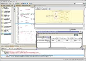
Figure 9 CDC verification is eased through debugging capabilities
Another important capability is a fully integrated debugging environment that allows users to seamlessly cross-probe between the CDC violation list, the RTL schematic and a waveform viewer. This allows the user to quickly find the source of CDC problems. That kind of cross-probing is much easier to do when debugging is an integral part of the CDC tools, rather than a separate, third-party tool. Single tool integration also frees the user from worrying about compatibility and interoperability issues. Figure 9 illustrates one type of debugger for CDC issues.
Conclusion
CDC verification can be greatly improved through a combination of capabilities lacking in traditional analysis tools. These capabilities include richer and more flexible structural analysis, along with functional, assertion-based analysis and integrated debugging. These features will allow new-generation tools that simultaneously minimize the false violations over-reported by traditional tools and detect the CDC violations the traditional tools miss. The potential ROI is enormous. By quickly eliminating CDC errors up front at the RTL level, enhanced CDC analysis can save companies millions of dollars in redesign and re-fabrication costs, cut months of development time and substantially improve the profit potential of products.
About the author
Shaker Sarwary is Vice President of SpyGlass Formal Verification Products at Atrenta. He has a doctorate from Paris University (France), and he has performed post-doctorate work at the University of California at Berkeley. He has held senior engineering positions in the areas of synthesis and verification at Lattice Semiconductor, Get2Chip, and Cadence.
