FPGA design for functional safety
Using triple modular redundancy, error detection and correction, and ‘safe’ FSMs to ensure greater functional safety in FPGA-based designs
Ensuring the functional safety of a design has always been important in industries such as medical, automotive, communications, industrial and aerospace. As the pace of innovation in these industries has increased, and their use of electronics has grown, so has their use of FPGAs. This has made it increasingly important to carry over functional safety techniques used in ASICs to FPGA designs for these industries.
Sharath Duraiswami, a corporate applications engineer at Synopsys, outlined some of the issues that designers need to address to improve the functional safety of PFGA based designs in a recent webinar. His presentation focused on mitigating the impact of single event transients, that is glitches on signal lines or in a memory fabric caused by an alpha particle or high-energy neutron strike. If such glitches are clocked into a synchronous element they can cause single-event upsets (SEUs) that corrupt the operation of finite state machines (FSMs), change logic values, register or SRAM contents, and even alter I/O signals.
The SEU problem is particularly critical in FPGAs, whose function is defined by programming. Different types of FPGA need different forms of mitigation, depending on whether they are programmed by Flash memory, antifuses or an SRAM array (see Figure 1).
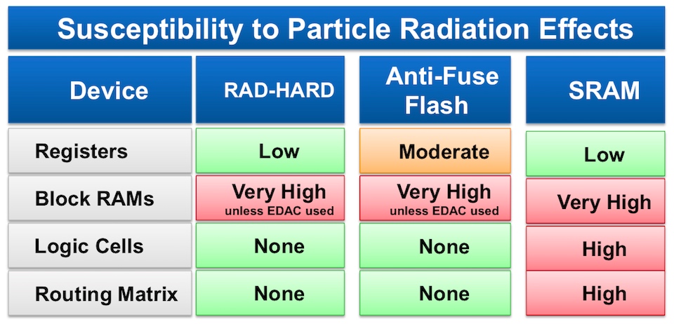
Figure 1 Functional safety protection strategies vary by FPGA type (Source: Synopsys)
Various approaches are available to address these vulnerabilities, including techniques such as triple modular redundancy (TMR), I/O replication, ‘duplicate with compare’ strategies for configuration memories, and the automated generation of ‘safe’ FSMs during synthesis in Synopsys’ Synplify Premier tool.
Triple modular redundancy
TMR, unsurprisingly, involves implementing three instances of a critical circuit in a design, and then using voting logic to ensure that all three instances come to the same conclusion. To do this well, designers should ensure three things: that the outputs of the triplicated circuits are directly connected to the voting logic; that any clocks and any inputs to clocks driving such circuits are synchronised; and that you tell the synthesis tool not to optimise away any nets you add in to monitor errors, and any custom logic that is designed to mitigate errors.
Duraiswami also outlined three different forms of TMR. (See Figure 2)
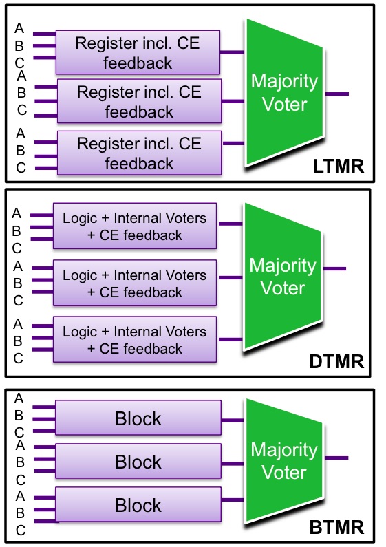
Figure 2 Three forms of triple modular redundancy (Source: Synopsys)
Deciding which to use means thinking through what sort of errors could be caused by errors in the block you are trying to protect, and how best to mitigate that impact.
- Local TMR can be used to protect registers, and includes feedback correction on synchronous Clock Enable (CE) signals
- Distributed TMR acts at the next level up the design hierarchy, protecting I/Os and logic. This approach alters the internals of the logic blocks to which it is applied, adding voting mechanisms and feedback correction for CE signals
- Block TMR is used as a ‘wrapper’ around circuitry that cannot be altered, such as third-party IP blocks, synchronising the inputs to the triply redundant blocks and voting on their output. It also separate the redundant blocks on the die, to reduce the chance of more than one block being affected by an alpha particle strike
Feedback correction is necessary because otherwise an erroneous output, caused an SEU in the output of one block of a TMR triplicate, could be held by its synchronous feedback loop and still present when an SEU in a second of the blocks also occurred, leading to an incorrect majority voter output. Synplify Premier can automatically add the voter output into the CE feedback loop, dealing with the issue.
Protecting memories
There are various strategies available to protect the onchip block RAMs on an FPGA. These include using TMR; inferring the use of special ECC RAMs in some Altera, Xilinx and Microsemi parts; and designing monitors that can trigger the wiping and reloading of memory, especially configuration memory, when an error is detected.
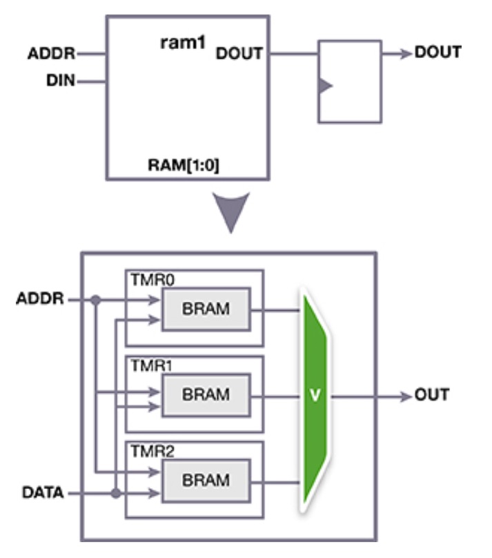
Figure 3 Applying TMR to block RAM (Source: Synopsys)
Protecting FSMs
The registers in an FSM define how it is supposed to react to any given set of inputs. If one of the registers suffers an SEU, a couple of issues can arise: the first is that the FSM keep running but moves to the wrong next state; the second is that it enters a state that is completely unanticipated and locks up.
One way to address this problem is to use synthesis to create ‘safe FSMs’, which are structured to protect themselves against SEUs in a number of different ways. For example, it is possible to build FSMs that include Hamming coding to detect and correct errors. Error recovery is possible with ‘safe FSMs’, which are structured during the synthesis process to return to a reset state when an error is detected. The most sophisticated approach, though, is to use synthesis to build “safe case FSMs’, in which the designer specifies a ‘default’ state in the case statement of their RTL that contains a user-specified error-recovery scheme.
Figure 4 Automatically implementing the logic for a ‘safe’ FSM (Source: Synopsys)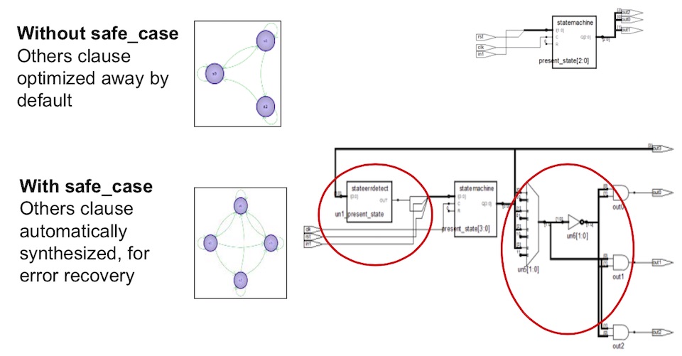
Mitigating I/O pad errors
SEUs at I/Os can be detected and corrected by replicating the I/Os or by applying distributed TMR strategies. In ‘duplicate and compare’ approaches, an error on an output pad can be mitigated by duplicating the module that drives the output, an the output pad itself. Error logic can be incorporated to flag the error for resolution.
A more advanced approach applied distributed TMR, triplicating the module that drives the output and triplicating the output itself. Any errors are corrected by majority voting.
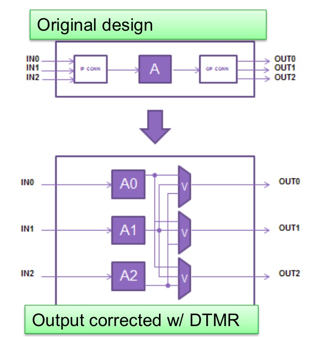
Figure 5 Applying DTMR to I/O (Source: Synopsys)
Duraiswami’s webinar has greater detail of the concepts behind each of these techniques, as well as details of how to use a combination of coding, synthesis commands and attributes in Synplify Premier, to control their implementation.
Further information
More on designing for functional safety with FPGAs
More on Synopsys’ Synplify Premier