Accelerating the development of powertrain ECUs with virtual hardware
How virtual hardware can speed up many aspects of automotive system development, including architectural analysis, software development and verification
Cars are rapidly becoming greener, safer, more connected and more secure. This is driving the evolution of vehicle architectures and systems, demanding the development of more complex hardware platforms, such as multicore systems on chip (SoCs) implementing advanced driver assistance systems (ADAS), more complex software to deliver these functions, and an evolving regulatory environment, such as the ISO 26262 standard, to ensure that future vehicles will be safe and secure.
This, in turn, is creating three challenges: development productivity for these more complex hardware and software platforms; a need for more testing for quality, safety and security assurance; and therefore, increasing development costs and cycle times.
Software is playing an increasing role, as OEMs rely on it more heavily to achieve goals such as greater fuel economy. The challenge here is that at the same time, MCUs are becoming more complex, with multiple cores and special functions such as complex programmable timers, while engine control units (ECUs) are also becoming more strongly integrated with other systems and functions in the car.
How can we affect the challenges of the development process? On the specification side of the usual V-shaped development process, the issues include whether a system architecture is optimised for performance, how developers can collaborate more closely with their suppliers to ensure that the microcontrollers they buy will meet their requirements, and how to start hardware/software integration earlier in the process. Once the system is ready, issues include finding ways to help developers achieve better quality sooner, and to check that safety requirements are being met earlier in the development process.
The traditional way of addressing these issues is to use simulation or virtual prototyping. The key issue with these techniques is how they are applied in each use case.
Architecture analysis
For example, these techniques can be used during the early architectural analysis and design work. For a systems company, such as the carmaker, the key questions they face at this stage are what the application use cases will be, how will the system be brought up and configured, what performance will it need, and what trade-offs will be necessary between cost and performance.
For the semiconductor company, working to fulfil the customer’s brief, the questions at this stage of the development include what the application workload will be, how that work will be partitioned and mapped onto the resources of the SoC, what kind of IP should be used, and what interconnection and memory architecture strategy should be applied.
In exploring these issues, a lot of the information necessary to satisfy both sides of this equation is held in silos within the companies involved, and exchanged between them in Word documents, simulations and spreadsheets. These static documents rarely provide enough detail to guarantee that the final performance of the device will match the user’s needs when the silicon is delivered.
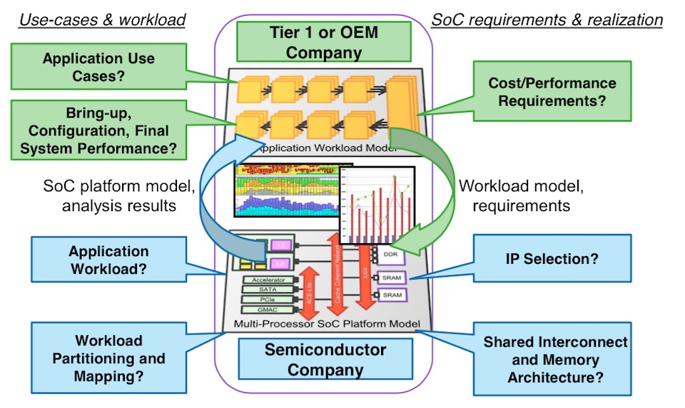
Figure 1 Improving information exchange in early architecture analysis using virtual prototyping (Source: Synopsys)
How can this information exchange be improved without exposing the proprietary information of the partners? One way to do this is to move from a static to a dynamic representation of the situation. For example, Tier 1 vendors and OEMs can develop application workload models that can be applied to a virtual prototype, of a multiprocessor SoC or even entire ECU, which can then be driven by the application workload defined by the user. With this approach, the SoC models can be simulated and the results analyzed so that performance can be measured and configuration optimised to meet the user’s real needs.
There are tools to help this task, such as Synopsys Platform Architect MCO, which helps create prototype models and models of the workload, and can then run the models to explore their interaction. The models can be assembled graphically and there is a runtime configuration facility for simulation sweeping and sensitivity analysis. The intent of the tool is to help architects achieve the right trade-off between performance, power and cost, without under- or over-design.
Software development and test
Software development and testing needs a different type of model, a processor model that can be used as a target of the software development process. It can be used to create a virtual hardware ECU, which provides an environment within which developers can run the embedded software as if it had been compiled for the real target architecture. This enables the software to be used within the simulation environment, to simulate interactions between the engine and the ECU, for debug, analysis and testing.
Virtual hardware ECUs tend to be used for a number of tasks such as the development of multicore software, complex drivers, algorithms, hypervisors and communication protocols. They are also used during integration test in virtual hardware-in-loop (vHIL) scenarios, for fault and coverage testing in support of ISO 26262 accreditation, and for automated regression testing.
For hardware/software integration, the current state-of-the-art is to begin software development between 9 and 12 months before the hardware is available. This enables tasks such as operating system ports and bring up, complex driver and communication protocol development, and algorithm development using a flow from a model-based environment such as Matlab through to embedded software running on the virtual prototype.
Virtual hardware ECUs can also provide a more efficient debug environment by offering complete visibility and control of the system, the ability to correlate hardware and software interactions, and the ability to do analysis in a non-intrusive way and in a deterministic environment. Such environments are also useful for tracking intermittent bugs, which can then be replayed for further analysis and solution. Some automotive Tier 1and OEM test teams report that using these approaches has enabled them to reduce their test times by 90%. Testing using virtual hardware also enables systems-wide analysis of the effect of device faults – a form of fault injection testing. Automated regression testing also means that the impact of any code changes can be quickly evaluated overnight for multiple versions of the software stack.
Virtual hardware-in-the-loop (vHIL)
Various approaches are taken to speeding up powertrain development, either by putting models, software, or processors in the loop. However, none of these enables the use of the real ECU hardware in the prototyping effort.
Using HIL makes it possible to evaluate a plant model against the real software that is in development. But the approach has limitations. Access to HIL systems tends to be limited, as is the debug visibility in such systems. It is also hard to employ such systems in regression testing, and they can be complex to set up, share, maintain and archive.
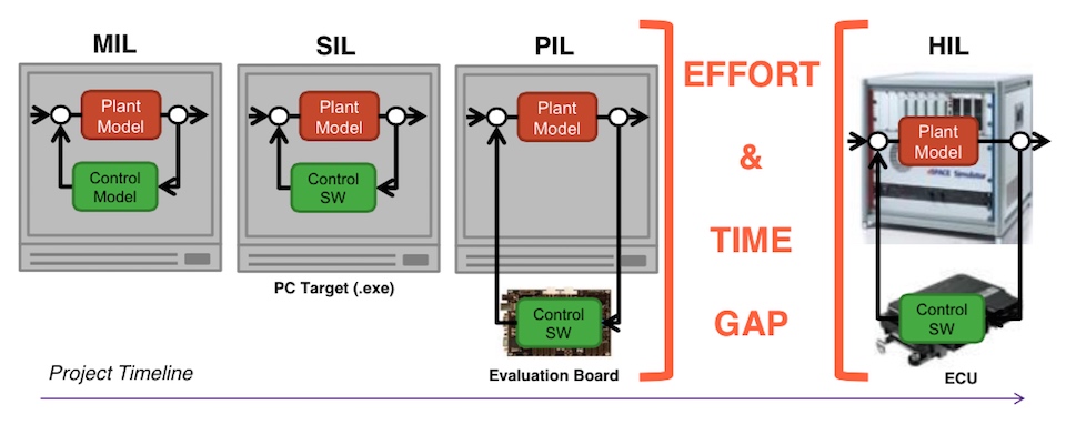
Figure 2 Some forms of ‘in the loop’ testing have limitations (Source: Synopsys)
It also takes time and effort to develop an HIL facility, which leaves the early phases of project development to find other ways to check their progress.
One way to bridge this gap and increase the development efficiency is to use a virtual HIL strategy, which can provide valuable insights even before testbenches become available. A virtual HIL, running on a PC, will include a model of the hardware ECU that can run the embedded software under development, and which can be co-simulated with a plant model.
To make this possible, a virtual hardware ECU needs to connect to the automotive tool ecosystem, such as Matlab, Simulink, Saber and Vector CANoe. This environment enables developers to start integration testing earlier, front-load their test development and execution, and use the whole system either interactively or in regression tests to identify integration issues more quickly.
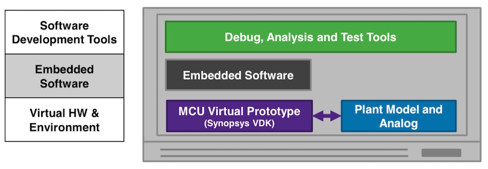
Figure 3 A complete simulation environment for powertrain development, using virtual hardware ECUs (Source: Synopsys)
The approach can also be used for other testing tasks, such as fault and coverage testing. Faults can be injected anywhere at the system level, to look at how the hardware handles them. The faults could range from a failed memory subsystem right through to a mechanical failure, with the simulation environment revealing how the embedded software responds to the fault.
Virtual HIL strategies also make it possible to modify the state of the whole system, and to inject permanent faults. Using a virtual hardware ECU also means developers can control and analyse the impact of faults more readily. Control can be triggered by software, hardware or timers, and all the resultant hardware and software events can be recorded and correlated in a nonintrusive way. It is also then possible to repeat the tests in a deterministic way, including in extensive overnight regression sessions.
Better productivity through faster regression
Another advantage of a virtual hardware ECU and virtual HIL strategies is that the whole system and its simulation environment can be easily duplicated across a server farm to enable faster regression through parallelisation. This could be used, for example, to validate the impact of changing a core function, such as a device driver, on a number of software stacks that have been built for a series of different vehicles. Automated regression testing on large server farms overnight could be set up to provide simple pass/fail indications of whether a change to the driver had affected any of the variant software stacks.
An example: the Bosch Generic Timer Module
The Bosch Generic Timer Module (GTM) is a semi-autonomous coprocessor IP block with a number of sub-modules that can be configured to offload issues such as I/O, signal processing, interrupt services, and safety features from a CPU. The resultant block can handle real-time interrupts, process instructions and create output waveforms. These basic functions can be combined into functions such as engine position evaluation, PWM generation, multichannel sequencing, and motor control.
But because the block has to be configured to offer the right hardware resources and programmed to offer the required services, developers need to create and validate the software to do this.
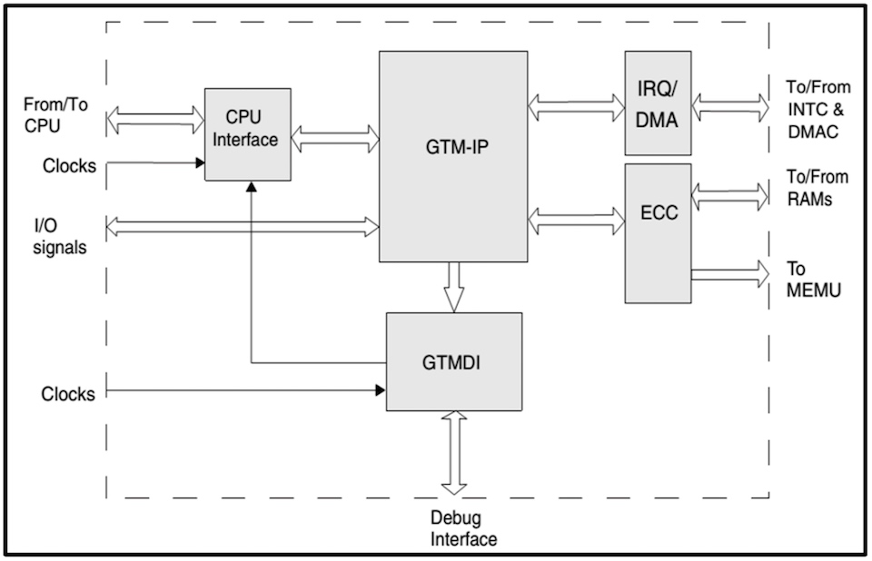
Figure 4 Integrating the GTM IP into a virtual MCU model (Source: Synopsys)
It is then possible to integrate the GTM IP block into a larger MCU model to create a virtual hardware ECU targeted for a specific application. The integration model typically handles tasks such as hard and soft reset for the GTM, controlling its operating mode, mapping the GTM’s registers to the system bus, generating interrupt requests and DMA requests, error detection and correction, and enabling GTM debugging. Use cases for the integrated model could include GTM driver and software development, and regression of GTM software tests.
Using virtual prototypes for developing powertrain MCUs
Microcontroller vendors such as Infineon, NXP, and Renesas, have worked with Synopsys to develop virtual models of their key automotive microcontrollers for use in this sort of virtual hardware ECU simulation environment. Organisations such as Bosch, Hitachi and GM have used virtual-prototyping techniques to accelerate the development of software and the debugging of hardware/software integrations.
It is still difficult to undertake a return on investment analysis for the use of virtual prototyping, and so we look at both quantitative aspects, such as productivity gains, and qualitative impacts, such as risk mitigation.
On the quantitative side, the major impact is on increased developer productivity, of up to 30% according to some Tier 1 and OEM users. On the qualitative side, some of the risk mitigation issues that are worth considering include the cost of discovering and finding issues late in the development process and subsequent product recalls, and the benefits of being able to launch products sooner. There are also issues such as the advantages of being able to do more and better testing, which may offset the impact of having to do the extra testing necessary to meet the demands of ISO 26262. There may also be benefits in improving communications within the supply chain, and in making it possible to decouple the software development and test process from the availability of hardware.
More info
- RoI Analysis White Paper: Using VDKs for Automotive System Development
- Web page: Prototyping in Automotive
- Web page: Automotive Ecosystem Collaboration
Author
Marc Serughetti is director of business development for automotive solutions and virtual prototyping at Synopsys. He has more than 20 years’experience in marketing and business development covering software development, prototyping, functional safety and vertical markets such as automotive, aerospace, industrial and consumer. Prior to Synopsys, Serughetti held senior marketing and business development leadership positions at Integrated Systems, Wind River and CoWare. He holds a master of science from the University of Washington, an engineering degree from ENSICA (France) and attended Stanford Graduate School of Business AeA executive institute.
Company info
Synopsys Corporate Headquarters 690 East Middlefield Road Mountain View, CA 94043 (650) 584-5000 (800) 541-7737 www.synopsys.comSign up for more
If this was useful to you, why not make sure you’re getting our regular digests of Tech Design Forum’s technical content? Register and receive our newsletter free.