Welcome to IJTAG: a no-risk path to IEEE P1687
Making a smooth transition to IJTAG, the scan-test strategy for IP blocks, without having to change your existing hardware.
You’ve heard all about IJTAG (IEEE P1687) [1,2,3], a new standard for accessing embedded test and debug features that makes it easier to integrate IP blocks and to retarget hierarchical (test) patterns [4,5]. You may also have heard that IJTAG is compatible with JTAG. The question now is what this means for your future test methodology. Can you use IJTAG on designs that use an in-house solution based on IEEE 1149.1 top-level test access and IEEE 1500 compliant cores? Can you try out IJTAG without any hardware changes?
The answer is yes. You can use P1687 on 1149.1/1500 compatible designs, without changing your hardware, and still reap some of the key advantages of IJTAG, such as automated test-pattern generation for any level of your product’s hierarchy. Here’s how.
Start with what you have
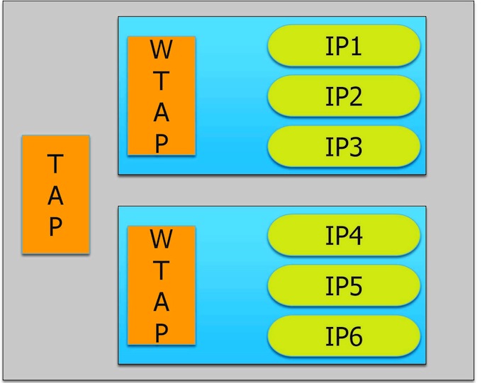
Say you have a design with a top-level 1149.1-compliant test access port (TAP) controller and a 1500-compliant wrapper TAP (WTAP) for each core (Figure 1), connected in any valid configuration. Assume that the embedded IP (IP1 through IP6) does not comply with the P1687 standard. This means that you cannot use P1687 to describe patterns directly at the IP level and have them automatically retargeted to the top level.
Figure 1
A test access mechanism using an IEEE 1149.1-compliant TAP at the top level and IEEE 1500 compliant WTAP for core access. (Source: Mentor Graphics – click image to enlarge)
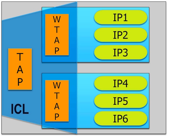
Instead, you can gain access to the IPs by modeling the WTAPs, and the operation of the IP blocks at their boundaries with the WTAP, in P1687. To be able to do this, you describe the TAP and the WTAPs as ‘instruments’, that is, IP with a P1687-compliant interface and behavior (Figure 2).
Figure 2
You can get going with IEEE P1687 by describing the TAP, the WTAP, and the connection in ICL. No hardware changes are needed. (Source: Mentor Graphics – click image to enlarge)
The behavior of the TAP and WTAP fulfils the requirements of P1687. [The hardware requirements of P1687 were derived from 1149.1 and 1500, so the TAP and WTAP are compatible with P1687 by definition.]
Describe what you need
P1687 defines two languages. The first, Instrument Connection Language (ICL), uses a set of keywords to describe the (test) input/output interface of instruments. For example, the ICL keyword ‘TMSPort’ says that an input port should be considered a TMS port as defined in IEEE 1149.1. Using these keywords, ICL defines syntaxes for each port, as well as a semantic, and a relative timing of events. The body of the TAP and WTAP ICL module definition is rather generic. The only variations come through the length of the registers, which can be parameterized, or any user-defined bits, ports, or opcodes.
In ICL, you can then define instances of modules and describe their connections, creating an ICL ‘netlist’. The ICL netlist for our example would only include three instances – the two modules and the top level. [If you would like a more complete example, feel free to email me.]
One feature of the ICL language is particularly helpful when defining a TAP or WTAP, because it lets you define a string representing a value, for example, using the ‘alias’ keyword:
Alias myUserOpcode1 = 5b’10100
You can also use enumeration tables, which are be bound to the registers for which they are valid:
EnumTable {
Reset = 5b’00000 ;
myUserOpcode1 = 5b’10100 ;
enableIP3 = 5b’01000 ;
…
}
Where is the advantage?
The benefit of aliases and enumeration tables becomes clearer when we consider the second language that P1687 defines: PDL, or Procedural Description Language. PDL is a command language that instructs an application tool how to generate patterns. It does not describe the patterns themselves, which may include control values to gain access to instruments. Instead PDL defines at the instrument level where (either a port or a register) to apply care bit values. The application tool follows the PDL instructions and retargets the care bits through the ICL hierarchy, automatically adding control values as needed. When the top-most ICL level is reached, the final PDL can be translated into any common pattern format, like STIL, WGL, or can be written out as a verification test bench.
Using the example design, here’s how you would enable the IP3 connection to the first WTAP (see Figure 2):
iWrite core1.instWTAP.IR enableIP3
iApply
This tells the application tool to generate a sequence of operations for the TAP and WTAPs that puts the bit-sequence 01000 in the instruction register ‘IR’ of the instance ‘instWTAP’ in ‘core1’. The ‘iApply’ keyword ends the instruction block.
Notice the absence of any user-defined control operations. What needs to be done to get the user-defined care bits ‘enableIP3’ into the specified location ‘core1.instWTAP.IR’ is up to the application tool and doesn’t concern you as the P1687 user.
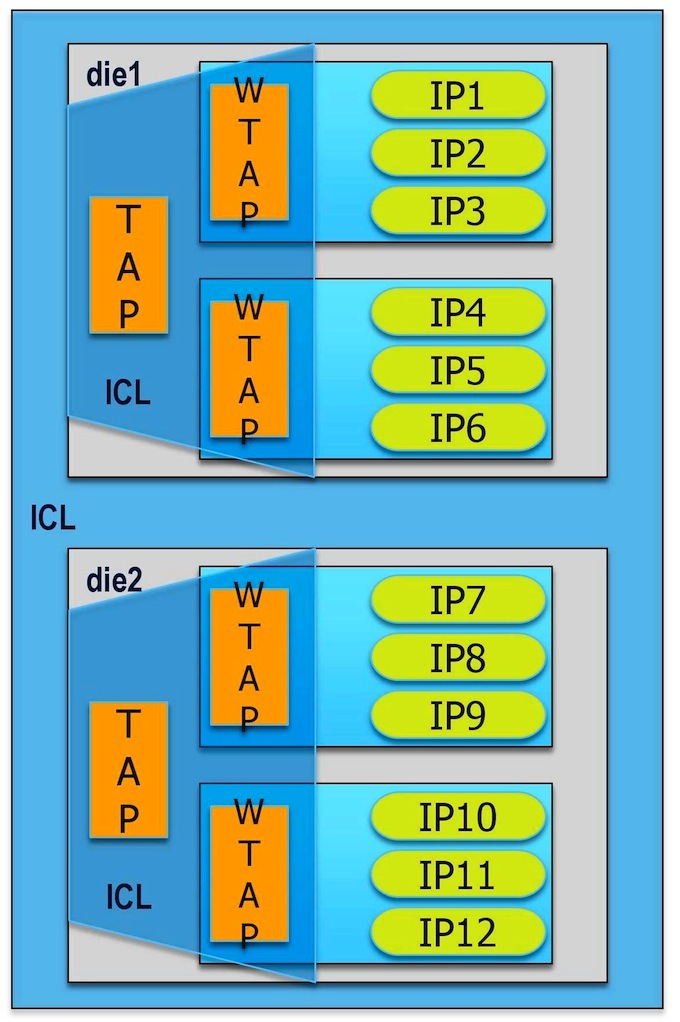
Let’s move the test one hierarchy level higher. Figure 3 shows two dice in a system.
Figure 3
Moving from die level to system level is painless in P1687. (Source: Mentor Graphics – click image to enlarge)
Again, you want to enable IP3. This additional level of hierarchy only slightly changes the actual PDL instruction, which now reads:
iWrite die1.core1.instWTAP.IR enableIP3
iApply
Compare this to the work involved in reusing a die-level validated test at the system level.
Now, what if you want to enable IP3 in parallel to IP12 (assuming the hardware allows this)? In PDL, this is simply:
iWrite die1.core1.instWTAP.IR enableIP3
iWrite die2.core2.instWTAP.IR enableIP12
iApply
With the goal of minimizing the overall scan operation and recognizing that the hardware allows it, the application tool will find a way to apply both opcodes at the same time to the two WTAPs.
Migrate your hardware step by step
In our example, we couldn’t assume that any of the IP blocks complied with P1687. Let us revisit this situation. Because they are controlled by a WTAP and probably receive and send data through the WTAP’s scan port, it is very likely that they are actually P1687 compliant or very close to it. If this is so, you would no longer need to address the IP block at the WTAP boundary but could talk directly to it and easily execute complex tasks such as an MBIST repair, leaving the WTAP operation to the application tool.
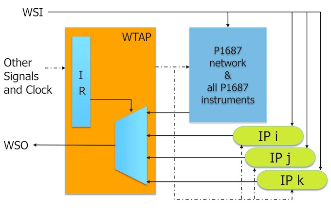
Figure 4 shows a situation in which some IPs are already migrated to P1687 and can be directly operated. The others remain proprietary and continue to be operated through PDL at the WTAP level. The figure also shows that all of the P1687 instruments can be added to a single P1687 access network. This network is under the control of the application tool, and allows it to further optimize access time to instruments and to improve the scan data volume. Over time, the entire WTAP may become redundant.
Figure 4
All P1687 components are in a network behind the WTAP, enabled through one WTAP opcode, for optimal P1687 access. (Source: Mentor Graphics – click image to enlarge)
Summary
Adopting P1687 on a design that already uses IEEE 1149.1 and/or IEEE 1500 is easy and doesn’t require hardware changes. The biggest advantages of P1687 in this scenario are the automation of generating tests for different hierarchy levels, and the general ease of use: you only need to define the care bits of the operation. The P1687 application tool applies them at the right time and in the right location, independently of how complex it is to access the IP. You can easily migrate IP to the P1687 standard piece by piece, mixing P1687 instruments and proprietary IP in the same design. P1687 offers a smooth transition from a proprietary in-house solution to an IEEE-standard backed commercial test solution.
References
1. The IEEE P1687 Working Group’s Web site is located at http://grouper.ieee.org/groups/1687/
2. J. Rearick, et al., “IJTAG (Internal JTAG): A Step Toward a DFT Standard,” International Test Conference, 2005.
3. K. Posse, et al., “IEEE P1687: Toward Standardized Access of Embedded Instrumentation,” International Test Conference, 2006.
4. B. Vermeulen, et al., “Overview of Debug Standardization Activities,” IEEE Design & Test of Computers, May/June 2008.
5. F. Ghani Zadegan, et al., “Reusing and Retargeting On-Chip Instrument Access Procedures in IEEE P1687,” to be published in Design & Test of Computers, IEEE.
6. M. Keim, R. Press, “What’s The Difference Between JTAG (IEEE 1149.1) And IJTAG (IEEE P1687)?” Electronic Design, May 16, 2012, http://electronicdesign.com, article ID 73938.
Author
Martin Keim joined the Silicon Test Solutions group of Mentor Graphics in 2001, where he is currently a technical marketing engineer. He is a member of the organizing committee of the International Symposium for Testing and Failure Analysis (ISTFA) and an active member of the IEEE P1687 working group. He holds several national and international patents and is author of many technical publications. He received a doctorate degree in informatics from the Albert-Ludwigs University, Germany. He can be reached at martin_keim@mentor.com.


The new IEEE 1149.1-2013 IJTAG standard already approved by the IEEE accesses IEEE 1500 Wrapper Serial Ports and supports segmentation of TDRs across power-domains not provided by P1687. BSDL has been extended to support a hierarchy of these descriptions without moving to a new “ICL” langauge. It would appear that it is more of a no-risk approach to on-chip instruments since one remains within 1149.1 and within the familiar BSDL.