Three essential steps to SoC design and verification
An evolved ESL-to-RTL methodology flow addresses the ‘discipline gaps’ between software and hardware engineering by using three system level-based software-hardware verification steps. The strategy is already available in TSMC’s Reference Flow 12.
Developing complex electronic systems involves a multi-disciplinary effort spanning electronics hardware, software, and system-level design. Arriving at the right feature-set, performance, power, and quality in both hardware and software has been difficult and costly due to gaps between these disciplines.
Fortunately, ESL-to-RTL based flows have recently evolved to address these goals in a methodical and scalable way that brings together the hardware, software, and system-level disciplines. As realized in TSMC’s Reference Flow 12 and, subsequently, within the Mentor Graphics ESL solution, such flows should include three ESL-based, software-hardware verification steps:
- Validate the application platform using ESL.
- Validate the design and new IP in isolation.
- Verify block and subsystem components within the context of the system.
1. Validate the application platform using ESL
One of the major challenges in developing an application platform, such as a mobile tablet, is to ensure that the platform works correctly in all possible modes of operation and that software running on the platform is validated and optimized before the hardware is implemented as RTL.
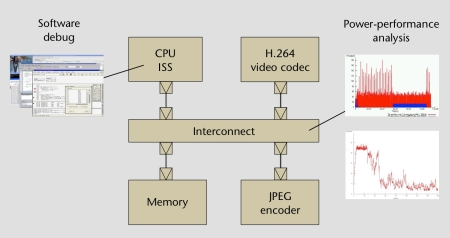
The first essential step involves building an ESL version of the platform with transaction-level models (TLMs) to validate the platform design and optimize it for performance and power.
Each of the TLM models represents a hardware block in the platform and is annotated with metadata to aid performance and power analysis. The TLM processor models in the ESL platform execute software that allows software developers to validate and optimize the OS, driver, and application-level software early on for both single and multi-core configurations.
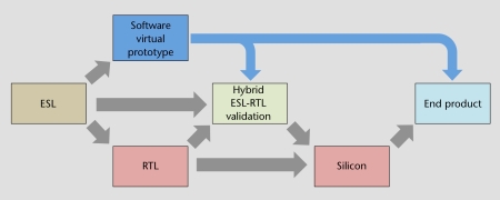
As the platform architecture solidifies to meet the design’s functional specification and when the platform is sufficiently optimized to meet performance and power goals, the software team can be given virtual prototypes derived from the ESL platform. These run in a native software development environment (IDE), allowing software engineers to complete development, validation, and optimization of the application software. In parallel, hardware teams can start implementing the RTL manually or by using high-level synthesis.
2. Validate the design and new IP in isolation
The underlying platform hardware will be based on existing design IP and a new hardware implementation. The second essential step is to validate these two elements in isolation and proceed with bottom-up integration and verification of the blocks into subsystems before integrating the subsystems with the software running on a processor.
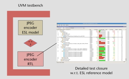
The requirements of RTL verification are much more detailed and exhaustive than those for ESL validation. They typically involve the use of constrained random techniques to explore corner cases that are difficult to reach by directed test stimulus.
To verify new hardware blocks, the TLM models from the ESL platform can be reused as reference models in a UVM RTL verification environment. The TLM model can be used to develop the UVM verification environment and the test case stimulus even before the design RTL is ready. It can then be used within a scoreboard to check that the design is behaving correctly under all required scenarios and that a sufficient level of functional coverage is being achieved.
3. Verify block and subsystem components within the context of the system
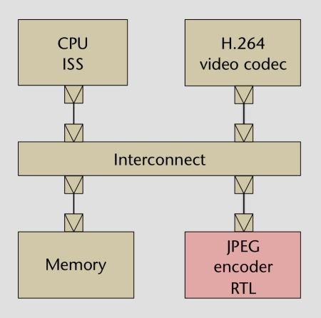
A common cause of system integration failures is that individual components meet their specification yet their system-level behavior is not correct. This leads to the third essential step. Once confidence in RTL functionality and quality across the blocks and subsystems has been established, functionality should be verified within the context of the system in a hybrid ESL-RTL platform validation environment.
This is used to validate the software interacting with the hardware blocks and subsystems on the platform, starting with driver code and then working up through the software layers to application code.
Going through this process early with an ESL platform allows low-level hardware-software interface issues to be debugged. Only then should validation be performed to ensure that the application software and the new block are implementing system-level behavior as expected.
Different tools are used at each level of software validation of the hybrid platform, each addressing specific validation objectives. These range from HW-SW co-verification tools focusing on the RTL, through ESL/RTL simulation, up to ESL/RTL acceleration on an emulator.
A checkerboard approach to platform validation can also be used. Different combinations of TLM blocks are swapped for RTL to validate different critical paths in the platform.
Flow overview
SoC verification has traditionally focused on RTL along the lines described in Step 2 (‘Validate the design and new IP in isolation’). Using these three steps allows an SoC to be validated and optimized for hardware and software performance in an integrated flow that encompasses both ESL and RTL and uses common reference models and platforms.

Figure 4. The software virtual prototype enables software to be developed concurrently with hardware (Source: Mentor Graphics)
This process validates the different aspects of an SoC in the most effective way and allows reuse of models within a consistent verification environment. For example, exploring trade-offs in architecture, power, and performance is easier in ESL, while practically impossible in RTL. Reusing the same ESL models in software and hardware development ensures that there is a consistent reference point throughout the verification flow.
Finally, enabling parallel software development using a software virtual prototype allows continuous crosschecks to be made on the SoC, using the various tools available within the flow, as both the software and the hardware are developed.
Contacts
Mentor Graphics
Worldwide Headquarters
8005 SW Boeckman Rd
Wilsonville
OR 97070-7777
USA
T: +1 503-685-7000
W: www.mentor.com


