FPGA-based prototyping 2: Understand the real cost
Part two of our series on FPGA-based prototyping looks at two critical factors to address before a project begins: budgeting and high-level implementation.
Part One of this series addressed the design and market drivers for FPGA-based prototyping. Part Two assumes that you have decided either to adopt the technique or extend its use. The board’s technical capability is important, but now you face some practical managerial questions. At the highest level, they fall into three categories:
- Functionality: What do you need the board to do?
- Time: How quickly do you need the board?
- Cost: What are the direct costs and related business costs?
The last of those is the most difficult to answer. It includes many intangibles and variables. For example, internal accounting standards will play a role. Your estimate will also need to cover the range of best-to-worst scenarios. And so on. However, there are traps that can be missed when you assess the ‘easier’ areas of Functionality and Cost.
There is not enough space here to provide a complete cost methodology for FPGA-based prototyping. But that’s not such a drawback. One of the main takeaways from this article is that, as with so much in chip design, “There is a tool for that, you know.”
After many years of working with partners and surveying the FPGA-based prototyping segment as a whole, Synopsys developed the Cost Comparison Spreadsheet (CCS). This asks you to input the important cost components within a project. The CCS will prompt you about parts of an estimate that might have otherwise been overlooked. But its overriding purpose is to give you a true sense of the cost, time and complexity involved – and how they can be controlled.
Our research and results already harvested from the CCS have allowed Synopsys to summarize six key components of any successful FPGA-based prototyping project. These are set out in the conclusion.
Before discussing the CCS in more detail, let’s look at the information you need to compile to best use it. This overview is organized around the three topics cited above: functionality, time and cost.
FPGA-based prototyping functionality
The starting point for an FPGA-based prototyping project has to be a clear assessment of what you want it to achieve. As we saw in Part One, the technique has extended some way beyond traditional validation of RTL by a simulator or emulator. We identified at least nine use-cases. They are worth repeating:
- In-system validation of your RTL;
- In-system test of algorithms and IP under internal development;
- In-system validation of external IP;
- Regression test for late-stage ECOs;
- In-system test of physical-layer software and drivers;
- Early app integration into embedded operating systems;
- In-system validation of software on a standalone target platforms;
- Early delivery of evaluation and software development platforms to partners; and
- Implementing a company-wide standard verification and prototyping infrastructure for use across multiple projects.
Some companies may see only one use-case as relevant and require only one board for it. Others may focus on just one option, but require multiple boards (the most obvious example of this is Option #9). Then there are those who may want to exploit several use-cases and/or their goals involve buying or building different boards for different teams (an example of that is where both software and hardware teams need dedicated resources).
The judgment calls here are not as straightforward as they appear. Board re-use is desirable, but not always optimal. For example, a complex board assembly with many test points to assist in debugging RTL (Option #1) may not be convenient or robust enough for use as a stand-alone software target (Option #7). Alternatively, an in-house board created to fit the form factor and price required for shipment to many potential partners (Option #8) may not have the flexibility for use in derivative projects (Option #9).
Another serious issue that now arises concerns the dilemma over whether to buy a vendor board or build one in-house. For example, the more boards that are used internally – with potentially a large amount of design reuse within the boards themselves – the more attractive the in-house option becomes. For Option #9, economies of scale may favor in-house development. However, there is a volume below which in-house prototyping board development becomes prohibitively expensive, and the economies of scale switch to favor the vendor option. How do you make that call?
Well, first, you need a clear idea of how you intend to exploit FPGA-based prototyping from the get-go. Yes, the more you use the technique, the more ways you may find to apply it. But that does not change the imperative that you have clear initial objectives.
FPGA-based prototyping time
Time is not just a question of how long it takes to synthesize, place, route and fire up your prototype. The first part of this decision goes back to build vs. buy.
Notwithstanding that boards used in volume might at some point favor ‘build’, there is the need to put the PCB in the hands of the appropriate team as early as possible.
The very largest players often have substantial internal expertise in FPGA and PCB design. They may therefore have a stock of prototyping boards ready for immediate in-house delivery. But you can probably count the number of such fortunately-resourced companies on the fingers of one hand.
Others going the ‘build’ route must remember that the board will need to be designed and delivered before the prototype can start being ported to it. That process will likely have four stages: development, layout, manufacturing and test. Each takes time.
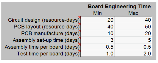
For, say, a complex 4-FPGA board with large, fine-pitch BGA packages, trace-length matching, and 25 or more layers, the layout time alone could easily be 40 working days.
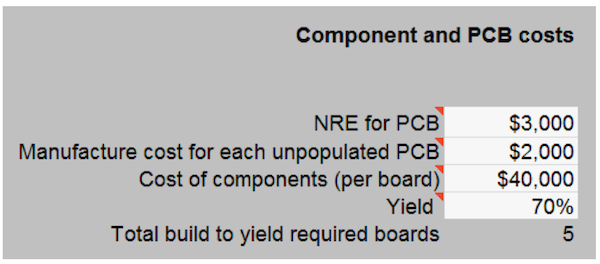
Then, there is the question of yield. Staying with the example of a complex board, an internal team might want to achieve around 70%. So how many boards will need to be made to ensure timely delivery to the design team?
Those last two factors are there for a design manager to consider apart from the universally recognized need to have substantial internal FPGA expertise whether you are implementing the prototype or designing the board that will house it.
Consider the third-party alternative. Boards are delivered from stock. The vendor absorbs the yield risk (and also will have been producing boards at a rate to take its yield much closer to 100%). The vendor’s business is based on dedicated and extensive FPGA expertise.
Having then bought rather than built, there are other inherent advantages.
You will have your own FPGA experts, but they will be able to consult with counterparts at the vendor.
A system such as Synopsys HAPS will also come with an optimized tool infrastructure. The latest tools are optimized to exploit parallelism and extract as much as possible both at the workstation and in the server farm (some of the most recent innovations in the HAPS tool infrastructure are addressed here).
Then, a vendor board will likely come with bolt-ons such as daughter boards that can be added to the system to accommodate design changes (e.g., IP added at a late stage). This represents another major advantage over in-house boards: They can be hard to reconfigure to embrace significant incremental additions or changes to a design.
At a high level, this extra support offers greater efficiency and faster delivery than internal processes. But from a budgeting perspective, the question is, ‘How much?’
Two things can help. Your time estimates for any project should use, where possible, results you have achieved on similar work in the past. Given the variables involved, this is your most reliable yardstick.
However, working again in close consultation with your board supplier will allow them to guide you based on their experiences in similar projects for other clients.
FPGA-based prototyping cost
A strict analysis of the likely use-case(s) and a well-informed analysis of how long your FPGA-based prototyping board will take to bring-up take you much of the way toward estimating the realistic cost of your prototyping project.
You should also now have some idea of the capital cost for your boards and associated tool licenses.
A good formal reading of your experience on earlier projects and close collaboration with internal and external FPGA and prototyping experts should provide a good measure of your best and worst-case scenarios.
And though we have not mentioned it until now, you almost certainly have a deadline for the overall ASIC project and can see how your prototype must fit into that schedule. Delivery of the ASIC not the prototype will primarily determine your ROI.
You have a lot of the data you need – but not all of it.
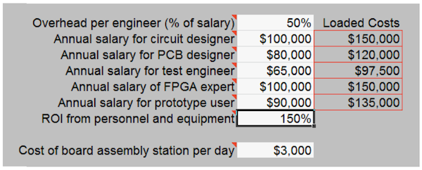
There is a substantial intellectual effort involved in FPGA-based prototyping. Personnel cost is one of the largest variables in any budget process, particularly when you weigh the build vs. buy equation. It is not simply a question of the time needed to build a board from scratch. That process also needs staff to perform the FPGA, PCB and test tasks.
Similarly at the prototyping stage, you need people. How much of that resource will be internal, how much external? What expertise does your prototyping team need? And what overhead is attached to each of those workers, from tool licenses to more mundane issues such as workspace and taxes?
Then what is your target ROI? Many companies work on the basis of, say, a 150%-200% ROI per employee (i.e., for every dollar in salary and overhead per engineer, the company expects to earn between $1.50 and $2.00).
Cost accounting also often requires some finesse, particularly in the context of corporate financial practices. Consider the following example.
An internally developed prototyping board may be considered a one-off R&D expense attributable in full to the project on which it is used. However, a vendor-supplied board may be seen as an asset that can be used across multiple projects and therefore its cost can be written off over time (typically, amortized over two years).
They don’t call accountancy an art rather than a science for nothing. For our FPGA-based prototyping project though, the purpose here is to illustrate the care with which direct and related costs must be assessed.
It is a process that patently requires your own understanding of how your enterprise works. But you will probably also need some external help, particularly if you are just adding FPGA-based prototyping to your flow.
The Cost Comparison Spreadsheet
Synopsys developed the CCS because budgets for FPGA-based prototyping must be drawn up with care. You face the build vs. buy question. You need to be clear about your prototyping objectives. You need to allocate resources appropriate to your corporate targets for time and ROI.
And you do not want your prototyping activity to take up a disproportionate amount of either the management or engineering effort. The ASIC is ultimately what matters.
These examples show how the CCS automates the estimation process based on data you have collected and Synopsys’ own experience of essential FPGA-based prototyping cost metrics.
Here, you can see variables for employee cost (Figure 1), time (Figure 2) and components on a ‘build’ project (Figure 3) as entered into the CCS to form part of the final calculation.
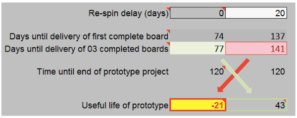
Figure 4 then shows an assessment of the board’s useful lifespan.
Access to CCS for your own project data can be arranged with your local Synopsys office. It will give you an informed view based on deep market knowledge and real-world results.
The six observations
The financial results from a system such as CCS can help you decide how to configure your own FPGA-based prototyping project. Each one has its own characteristics.
But, as we said at the outset, our experience suggests that almost all successful FPGA projects conform to six overarching principles. These inform how CCS works and again should also guide how you proceed so that you meet all your goals, financial and technological.
- The prototyping project is managed and performed by dedicated FPGA experts.
- Early consultation with prototyping experts is very valuable.
- Personnel cost is a significant portion of the prototyping project and usually larger than the difference in material cost between making and buying FPGA boards.
- Having early access to boards is critical especially in shorter prototyping projects (e.g., 6 months or less). One way to reduce the risk in prototyping is to ensure that the FPGA boards are available at the start of the project rather than developed during it. Early access to boards may be achieved in three ways:
- Re-usable in-house platforms that meet project requirements.
- Pre-designing and building project-specific boards before the project.
- Buying in and configuring standard boards from external supplier’s stock.
- There is a threshold of board volume below which it is uneconomical to design and build boards in-house. Even for higher volume prototyping projects, time and risk may outweigh the economic factors.
- The overall ASIC project represents a very much larger investment than the prototype boards. Missing the market window for the product in which the ASIC is used may be the biggest cost of all.
Having armed yourself with a good idea of the real costs involved in FPGA-based prototyping, the next part of this series addresses the choices you face in building or buying the right kind of board for the job. Boards come in various configurations and with different capacities. You need to make an informed choice here too.


Author follow-up:
The Synopsys FPGA-Based Prototyping Methodology Manual (FPMM) co-authored by Doug Amos (Synopsys), Austin Lesea (Xilinx), and Rene Richter (Synopsys) offers a detailed treatment of prototype development and maintenance costs along with worked examples (www.synopsys.com/fmm).