Six ways to exploit the advantages of finFETs
TSMC has released its fourth major 16nm finFET process, 16FFC (16nm FinFET Compact), into volume production. To take advantage of the process’s power, performance and area (PPA) advantages, designers must combine process-aware design strategies with optimized IP, including standard-cell libraries and embedded memories. Here are six ways to do that.
Take advantage of process scaling
The 16FFC process has a smaller transistor pitch (contacted poly pitch), smaller metal pitch (wire to wire, via to wire and via to via) for routing, and smaller bitcells, than TSMC’s 28nm process, to enable 16FFC to exceed Moore’s Law node-to-node scaling of area and performance. FinFETs also have a higher saturation current per unit area, which can boost performance in shorter logic cells. IP designers can take advantage of these reduced process dimensions and improved transistor performance to build smaller/faster cells and memories. SoC block designers can use these advantages to close critical timing paths, but must account for higher wire delays due to thin, resistive wires and electro-migration concerns for signal wires and the power grid.
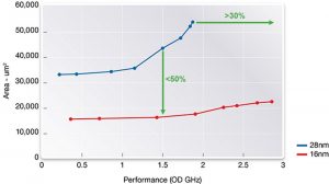
Figure 1 shows that with the right IP, 16FFC designs can exceed Moore’s Law scaling with less than half the area and more than 30% faster than the same designs implemented on 28nm.
Figure 1 Area vs performance – 28nm vs 16nm for CPU (Source: Synopsys)
Balance reduced gate leakage with increased dynamic power
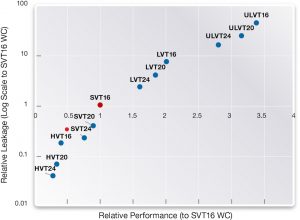
The 16FFC process offers a variety of threshold voltage (VT) and channel-length choices to serve various performance and leakage trade-off conditions. Figure 2 plots logic gate performance vs leakage (on a log scale) to show the tradeoffs that can be achieved using standard cells with identical footprints at various VT and channel lengths.
Figure 2 Relative performance vs relative leakage per VT and channel length, 7.5 track (T) ultra high density (Source: Synopsys)
Many mobile and Internet of Things devices spend most of their time in standby or sleep states, where the only power dissipated is through leakage. FinFETs have a higher Ion/Ioff ratio, due to their vertical fin structure. FinFETs can also operate at lower voltages than traditional planar devices, further reducing their leakage.
Total power is the combination of dynamic and leakage power. FinFETs have less leakage than planar nodes but consume relatively higher dynamic power due to the increased input capacitance of the fins and the higher saturation currents they produce.
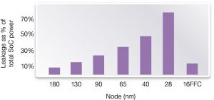
This change in relative leakage vs dynamic power demands a change in design approaches to those taken at 28nm. Figure 3 shows leakage power as a percentage of total SoC power from 180nm to 16nm. It demonstrates that designers working with finFETs can worry less about reducing leakage than on planar processes, but must work harder to control dynamic power.
Figure 3 Leakage as a percentage of total SoC power from 180nm to 16nm (Source: Synopsys)
Manage the dynamic power of finFETs
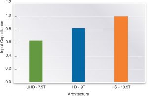
Designers can control dynamic power by managing switching frequencies through aggressive clock gating, reducing capacitances and minimizing operating voltages. Wiring capacitance is reduced with dense, optimized layouts and shorter wiring runs. Input capacitances can be minimized by using libraries optimized with the best cell heights for a given function at a given frequency. Standard cells can be built in multiple heights (with integer multiples of N and P fins) to match the target frequencies of the different blocks in both performance and reliability. For example, Figure 4 shows the input capacitance of 1X drive inverters at three different track heights (7.5T, 9T, 10.5T).
Figure 4 Input capacitance of 1X inverter per standard cell architecture (Source: Synopsys)
Depending on the block function and frequency, using the Ultra High Density (UHD) 7.5-track library for a block will not deliver as much performance as the High Density (HD) 9-track library for the equivalent block, but will consume ~25% less power, due to its reduced device capacitance.
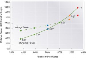
Dynamic power can also be reduced by a factor of V2 by lowering operating voltages, as shown in Figure 5, which plots the leakage power (dotted line) and dynamic power (solid line) of comparable blocks at different nominal voltages.
Figure 5 Performance vs leakage and dynamic power at multiple nominal voltages (Source: Synopsys)
Optimize logic library design
One of the most important ways to get the most out of TSMC’s 16FFC process is to ensure that the logic library you use is optimized for maximum routed block density. There are a number of ways to achieve this:
Efficient layout to reduce area and total power
It is important to take full advantage of process features such as the availability of continuous poly on diffusion edges, which enables routed blocks to be 5% smaller than a design using only poly on diffusion edges.
Combinational cells
Optimizing register-to-register paths requires a rich standard-cell library that includes the appropriate functions, drive strengths, and implementation variants. These functions are necessary for synthesis to create efficient circuits. Optimized layout techniques are needed to get the most out of the latest routing algorithms and so maximize pin access and reduce or eliminate congestion. Advanced synthesis and place-and-route tools can take advantage of a rich set of drive-strength options in the cell library to handle the different fan-outs and loads created by the design topology and physical distances between cells.
Sequential cells
The setup and delay time of a flip-flop is sometimes called its dead time, and eats into the useful time available to do real computational work in each clock cycle.
Use the different flip-flops wisely
It’s possible to use multiple sets of high-performance flip-flops to manage this dead time. Delay-optimized flops (multi-delay flops) can rapidly launch signals into critical-path logic clusters. Setup-optimized flops (multi-setup flops) serve as capture registers to extend the available clock cycle in multiple increments. Synthesis and routing optimization tools can be constrained to use these multi-setup/multi-delay flip-flop sets to achieve 15-20% performance improvement using advanced techniques such as useful skew.
Memory compiler design
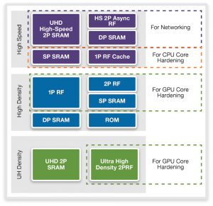
DesignWare Memory Compilers have power-management features such as light sleep, deep sleep, shutdown and dual power rails, and write-assist. They are also closely coupled with the DesignWare STAR Memory System, which provides an embedded-memory test solution to detect and repair manufacturing faults.
Figure 6 DesignWare Memory Compilers for a variety of applications (Source: Synopsys)
Summary
TSMC’s 16FFC process has improved process rules for area, transistors for performance/power, and reduced variability to enable smaller designs at higher performances, using less power. To take full advantage of the process, designers need access to a combination of optimized IP blocks, logic libraries and memory compilers, as well as synthesis and place and route tools that can apply them to best effect.
Further information
For more information, visit: http://www.synopsys.com/dw/ipdir.php?ds=hpc-design-kit
Author
Ken Brock is product marketing manager for logic libraries at Synopsys. Prior to Synopsys, Ken held marketing positions at Virage Logic, Silvaco, Virtual Silicon, Compass Design Systems, Mentor Graphics and Silicon Compilers. Brock holds a Bachelor’s Degree in Electrical Engineering and an MBA from Fairleigh Dickinson University.
 Ken Brock is product marketing manager for logic libraries at Synopsys. Prior to Synopsys, Ken held marketing positions at Virage Logic, Silvaco, Virtual Silicon, Compass Design Systems, Mentor Graphics and Silicon Compilers.