Improve your LVS debug productivity
The two primary building blocks of design verification for SoCs are design rule checking (DRC) and layout vs. schematic (LVS) verification. DRC focuses on meeting physical constraints and requirements in the layout, while LVS compares the schematic netlist to the design layout to ensure that the physical circuitry will operate as designed. With today’s highly dense and hierarchical layouts, increasing circuit complexity, and intricate foundry rules, running LVS can be a time-consuming and resource-intensive endeavor. These days, full-chip LVS runs not only compare the design layout against the schematic netlist, but also typically include additional verification steps, such as electrical rule checking (ERC) and isolating shorts, which also increase LVS runtimes.
Of course, running LVS is only one of the ways in which LVS checks absorb verification time and resources. Debugging LVS results for large designs can be extremely time-consuming, depending on the complexity of the design. For example, resolving shorts between power and ground nets can be difficult and time-consuming, due to the fact that power and ground grids form large nets that extend across the entire design, and due to the wide variety of possible causes for a short. Similarly, identifying discrepancies when comparing a layout to a schematic can be arduous, as they can have many causes, and keeping track of corresponding elements in very dense designs is laborious.
Designers who want to get to LVS-clean results for their high-performance designs as quickly as possible need a more effective and efficient methodology for finding and fixing LVS errors. The first step is to understand how and where they occur. Traditionally, the LVS process is dominated by two phases: extraction and circuit/layout comparison. An LVS tool is used to extract a netlist from the layout, using device and net connectivity extraction techniques. Next, the tool compares the extracted layout netlist to the schematic netlist. Errors found during either extraction or comparison must be debugged. This is usually where the biggest hits to your turnaround time begin to happen. Let’s look at why…
During connectivity extraction, the assignment of multiple text names to the same polygon may leave the extraction process unable to clearly assign a net to that polygon. When this occurs, the extraction process selects one of the assigned names (with power having priority over signal) and identifies a “texted” short in that net. These texted shorts are typically one of the major debugging issues in the extraction phase. Debugging these shorts can be tricky, given that they can have many different causes and can cross design hierarchies. Large nets such as power and ground nets can often extend over an entire layout area, contain many polygons, and span multiple hierarchies, making a shorted power-ground net difficult and time-consuming to debug.
Time is also an issue when debugging discrepancies between the extracted layout netlist and the source netlist. Because today’s designs are incredibly complex, involving numerous devices and multiple hierarchies, designers often need significant time to match the equivalent elements in the layout and source netlists, and eventually track and resolve the cause of these discrepancies.
Whether designers are confronting shorts on a long power net, or debugging comparison mismatches, more effective and efficient LVS debugging techniques can help them improve productivity and reduce time to tapeout. EDA tools are evolving to provide designers with more debug assistance, helping them find and solve LVS issues faster and more accurately.
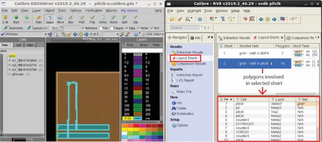
For example, designers who use the Calibre toolsuite from Mentor, a Siemens business, can now activate a short isolation process when running the Calibre nmLVS tool. This process generates a shorts isolation database containing a comprehensive list of all the shorts in the layout. The Calibre RVE results viewer provides an interactive short isolation debug flow that uses this database to display the individual polygons extracted for shorted nets (Figure 1). This information enables designers to quickly and systematically debug the shorts in an orderly way, starting with the most critical shorts first. They use their knowledge of the layout and design to examine and assign a net label to all the polygons in a short. Polygons that are deemed to be a potential cause of a short are assigned a REMOVE label.
Figure 1 Designers can select and highlight a short, and review the polygons making up the short
Once all the polygons are labeled, designers can launch a shorts verification run (not a full LVS run) that determines whether or not the short would be eliminated if the polygon marked REMOVE was not in the shorts database. This process does not actually remove the polygon from the layout; it simply removes the polygon from the shorts database during this focused verification run.
If the shorts verification run confirms that the shorted path no longer exists (and there are no other shorts between the two nets), the short is labeled as virtually fixed. If results show that one or more shorts still exist at other locations between the nets, a new set of the polygons comprising the shorted path are shown, and designers continue working through this new set of short polygons until they find the offending polygons. At any stage of the analysis, if they believe they have removed the wrong polygon(s), designers can go back to the original shorts database and start the analysis over again.
Once all the offending polygons have been identified and the short is virtually eliminated, designers physically remove the shapes from the layout using a layout editor and initiate a full LVS run to confirm that all the shorts have been corrected. By using this interactive shorts isolation process, designers can more quickly and systematically debug and fix shorts without the need for multiple full LVS runs.
In the comparison phase, designers often encounter discrepancies such as cross-connection errors, bad instance-connection errors, open-circuit errors, short-circuit errors, and pin-swap errors. Debugging discrepancies revealed by comparing the layout and schematic has typically required designers to manually track and manage the corresponding elements while analyzing each discrepancy for its root cause. In very dense designs, this quickly becomes a time-consuming and frustrating task.
To speed up and improve LVS discrepancy debugging the Calibre RVE results viewer now suggests possible fixes, which designers can review during debug. These suggestions provide likely causes for a discrepancy, making it easier for designers to perform fast, detailed error analysis.
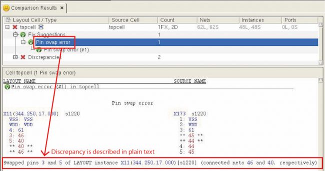
Let’s use a simple pin-swap error to walk through the process. Pin-swap errors occur when two layout pins of an instance are cross-connected. Once the layout/schematic comparison is complete, designers can view a clear textual explanation of the pin swap discrepancy.
Figure 2 A simple text description referring to the possible origin of discrepancy is provided
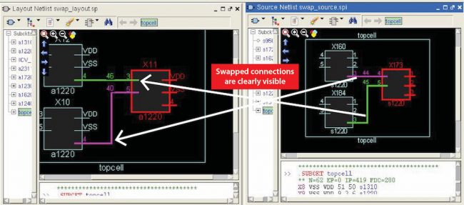
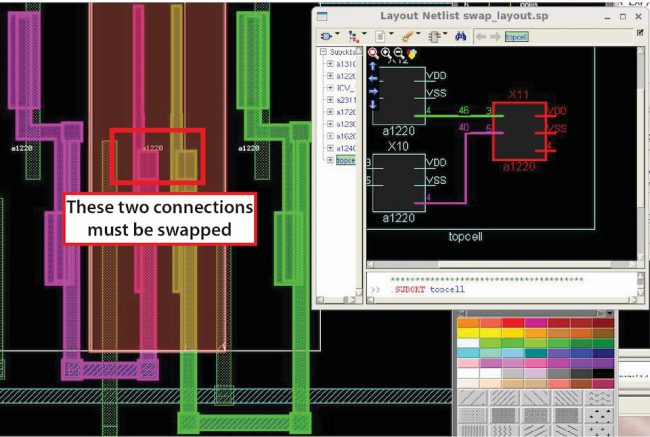
With this information, designers can highlight the instance (X11) and the two nets (46 and 40) involved in the discrepancy, in both the layout design environment and the schematic viewers (layout and source). Comparing the internal schematic views enables designers to see the swapped connections (Figure 3); referencing the layout highlight with the highlight in the layout schematic viewer lets them see which connection must be corrected (Figure 4).
Figure 3 Highlights in internal RVE schematic viewers help visualize the discrepancy
Figure 4 Viewing highlight in the layout viewer vs. the layout schematic viewer shows which connections must be swapped
Because LVS is required for signoff, the productivity of the LVS debug process directly impacts the project plan and tapeout schedule. With today’s dense designs and complex rules, the process can be daunting and time-consuming, unless designers have access to debugging options and techniques that make it faster and more productive. Adopting enhanced LVS debugging techniques such as interactive short isolation and discrepancy fix suggestions reduces the need for multiple full LVS runs, and enables designers to more quickly identify and resolve the root cause of LVS errors. This enables design teams to complete design verification more quickly and confidently, reducing tapeout schedules.
For more information, download our whitepaper, Improving productivity with more efficient LVS debug
Author
Raghav Katoch is a product engineer with the Calibre physical verification team at Mentor, a Siemens business. He works with customers to improve their physical and circuit verification flows, while also focusing on tool optimization within the Calibre toolsuite. Katoch received a BE in electrical and electronics engineering from the Birla Institute of Technology and Science, and an MSc in electrical engineering from the University of Texas at Dallas. He may be reached at raghav_katoch@mentor.com.
 Raghav Katoch is a product engineer with the Calibre physical verification team at Mentor, a Siemens business. He works with customers to improve their physical and circuit verification flows, while also focusing on tool optimization within the Calibre toolsuite. Katoch received a BE in electrical and electronics engineering from the Birla Institute of Technology and Science, and an MSc in electrical engineering from the University of Texas at Dallas.


