Creating a rugged standard for embedded memory
Most memory module standards have not been specified with particular reference to extreme environments where shock and vibration may present significant risk. Rather, designers have had to use a number of workaround techniques, strapping or even directly soldering devices to the board. In addition, the drive toward smaller board sizes is presenting a number of challenges at this end of the embedded computing market. In response, the Small Form Factor Special Interest Group gathered some of its members last year to develop a rugged module standard. Only a few months later, the standard has been agreed upon and the first products are already available.
For years, designers of small form factor, off-the-shelf embedded CPU boards—both single board computers (SBCs) and computers-on-modules (COMs)—for use in rugged applications with significant resistance to shock and vibration, have been faced with difficult design decisions for their main memory.
Standard memory expansion interfaces such as DIMM and SO-DIMM are not designed for these rugged applications. Therefore, there has been significant concern over the use of such standard expansion technologies, and there have been cases where, especially for military applications, SO-DIMM usage has been explicitly specified as unacceptable.
Designers have consequently resorted to two types of solutions, although each has significant drawbacks.
In some cases, an add-on retention mechanism has been added to a standard memory expansion installation. Clips, straps, glue or other tie-down mechanisms have been used to prevent a SO-DIMM from flying out of its socket. However, this approach does not deal with issues relating to the socket itself. Concern persists that movement of the expansion module within the socket—typically one of the comparatively inexpensive, commercial-grade sockets used in laptops—can lead to intermittency in pin connections that in turn can bring a system down.
The second solution has involved soldering memory chips directly to the CPU board. While this approach deals with shock and vibration issues, it still has three significant drawbacks.
The first is the board space consumed by the memory components. As CPU boards shrink in size, this space is extremely valuable.
The second is the wide variety in memory requirements for ‘rugged’ applications. Each memory configuration must be manufactured individually. The manufacturer therefore faces either the maintenance of a large number of SKUs for different memory configurations (a problem that can be compounded by forecasting and inventory issues), or the need to place restrictions on the number of products to a point where the company may not be able to offer the appropriate memory configurations for some applications.
The third and final issue here is that once the memory is soldered to a CPU board, there is no way that it can be realistically replaced or upgraded after the original manufacture.
In this context, the Small Form Factor Special Interest Group (SFF-SIG) has developed the RS-DIMM (Rugged Small-outline – Dual In-line Memory Module) standard.
It provides off-the-shelf, commercially available rugged memory expansion modules of varying capacity, allowing the module manufacturer to offer multiple memory size solutions to an OEM while maintaining a single CPU SKU. Space occupied on the CPU board is limited to the connector and mounting hole locations. Enhanced ruggedness is obtained through the use of a high-performance 240-pin socket connector system and the use of standoffs with screw attachments firmly holding the CPU and memory module together.
Toward a specification
The SFF-SIG Rugged Memory Working Group first convened in July 2010, starting its work from a completely blank piece of paper. The group was composed of connector, memory module and CPU board suppliers.
Given the challenges outlined above, the group first worked on a set of goals against which it could measure various alternative options and the progress being made toward a new standard. Fairly rapidly, it became apparent that there were two most promising candidates for the new standard.
The first would be based around a mezzanine card and would use a pin socked similar to those encountered on COMs.
The second approach would involve use of an extended module for the SO-DIMM profile with mounting holes added.
Given a recognition that the group could only realistically go forward with one of the two options, it decided after much discussion to adopt the mezzanine card-based approach.
A major concern here was the possibility of module movement within a commercial grade SO-DIMM socket for reliability reasons stated earlier.
This key decision having been taken, the group then worked on putting together a more detailed interim specification.
By October 2010 it was ready to ask the wider SFF-SIG membership (and some CPU board suppliers outside the organization) to ‘test drive’ this version and provide feedback.
At this time, the working group discovered that there was a class of SBCs where the SO-DIMM was too large for use. By reducing the longer dimension of its proposed rugged module to 67.5mm from the more traditional 72mm, there was an opportunity to open up the new specification to a further class of applications for which size was more important than ruggedness.
Responding to this and other feedback, as well as continuing internal discussion, further refinement of the standard continued through November and December of 2010.
This also included the subjection of the module to a shock and vibration test using a COM Express CPU, which found that it conformed to the appropriate ANSI/VITA 47-2005 (R2007) specifications.
The six active members of the Rugged Memory Working Group finally reviewed and voted to send the specifications to the wider organization for vote in January, and the first products confirming to the RS-DIMM specification were announced in February.
RS-DIMM in detail
Here are some of the main features of the new specification.
- The specification defines a 67.5 x 38mm module that stacks 7.36mm above a CPU board.
- It uses DDR3 technology and is specified for both unbuffered and registered implementations.
- Memory sizes up to 4GB, with option error correction circuitry (ECC) are supported using either 9-chip or 18-chip designs.
- Ruggedness is achieved by using a high-speed Samtec 240-pin BTH/BSH connector pair on the memory module and CPU board, along with two mounting holes.
- The RS-DIMM does not have the two socket ‘wings’ that hold an SO-DIMM in place, so its modules will fit on smaller form factor boards (e.g., Processor AMC modules) that cannot accept SO-DIMM’s 72mm dimension.
- •The pin definition closely aligns with that for SO-DIMM so that it is easy to adapt an existing design to the new rugged specification, even though this is not formally compatible with current JEDEC memory devices.
The specification itself includes the board outline, location of mounting holes for positive attachment to the underlying CPU board, connector definition and placement, and pin definition. It is available to download free of charge from the Interest Group’s website (www.sff-sig.org).
A few further technical observations about the specification should be made. It has been decided not to retrofit RS-DIMM to DDR2 devices. Most new devices are likely to be designed with DDR3 and the next step in advancing the standard in this regard is likely to be the addition of DDR4 capability.
Designs that incorporate solid state drive or flash memory entail the use of valuable board space for either the devices themselves or their connectors. The RS-DIMM specification includes a SATA interface that allows for the possible implementation of dual function modules (e.g., DDR3 + flash).
Support at launch
As noted at the outset, a key driver behind any new standard is that it should allow a group of suppliers to coalesce around its support with a range of appropriate product offerings, particularly where cost reduction, as well as technical harmonizations, are necessary.
In the case of RS-DIMM, two memory module suppliers, Swissbit (www.swissbit.com) and Virtium Technology (www.virtium.com), are supplying products already.
Virtium is offering a 4GB unbuffered RS-DIMM in a 1.5V PC3-10600 module. It is available with thermal heat-spreader, thermal sensor, conformal coating, and underfill protection options.
Swissbit is offering densities of both 1GB and 2GB for the latest Intel-based embedded platforms and other DDR3 ECC-capable applications at PC3-8500 and PC3-6400 speed grades. Modules are also available with operating ranges for both commercial temperature grade (0° to 85°C) and industrial temperature grade (-40º to 95°C).
Lippert Embedded Computers has meanwhile developed a RAM-module, capable of holding 18 RAM chips within the dimensions of the RS-DIMM standard.
Beyond this, SFF-SIG is rolling out a number of reference designs on its website, although these will be available at this time to members only. Sample orientation can be seen in Figure 1 (p. 57) and routing in Figure 2.
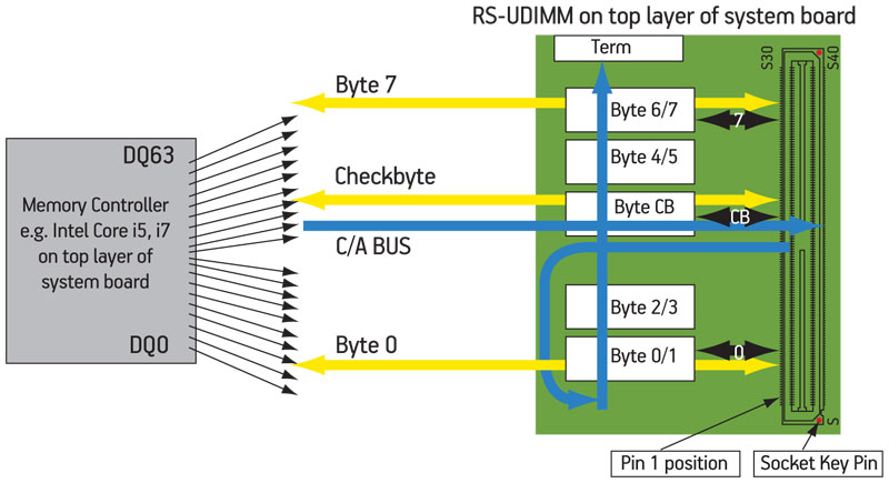
Figure 2
Routing overview with module placement in Figure 1
Source: SFF-SIG
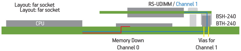
Figure 1
Module orientation on CPU board vis-à-vis processor/chipset
Source: SFF-SIG
“The RS-DIMM specification is the first standardized off-the-shelf memory solution for designers of rugged small form factor CPU boards,” said Paul Rosenfeld, the Interest Group’s president.
“I am thrilled that we now have an elegant adoptable standard that can be used to replace the extremely limiting soldered memory solutions, as well as half-baked strap or glue remedies previously used with commercial-grade memory modules.”
SFF-SIG
2784 Homestead Rd., #269
Santa Clara
CA 95051
USA
T: +1 650 961 2473
W: www.sff-sig.org