Addressing portable medical device needs
The development of medical devices, particularly portable medical devices, is expensive, and the time-to-market is long. Yet, social trends are making these one of the most exciting product segments for the embedded systems market. The article reviews key decisions a device designer must make in terms of the MCUs and other silicon and software that surround them as well as the need for highly integrated, ultra-low-power strategies.
The aging of the world’s population is a trend our society is working hard to address. Baby boomers are becoming senior citizens, and to accommodate this dramatic population shift, major changes in our health systems are necessary. We will need new therapies and early diagnostic tools based on advanced hardware and software technologies that are accessible to the general population. Portable medical devices will deliver a vast majority of these new therapies, such that iSuppli forecasts 10% year-on-year growth for the Portable Medical Segment.
Unlike many other electronic products, medical devices face a necessarily deep regulatory approvals process. A 2004 article in the Journal of the American Heart Association estimated that the pre-clinical research and development costs for a medical device can be between $10M and $20M, and that the work will typically take several years, involving a multi-disciplinary team of clinicians and engineers. NREs are high and time-to-market is long. This necessitates a much higher level of rigor in the hardware and software selection process.
Figure 1 shows a basic block diagram for a portable medical device. Notice that it incorporates several key pieces of technology and each of these must be evaluated before a hardware platform can be selected for use within the application. These are:
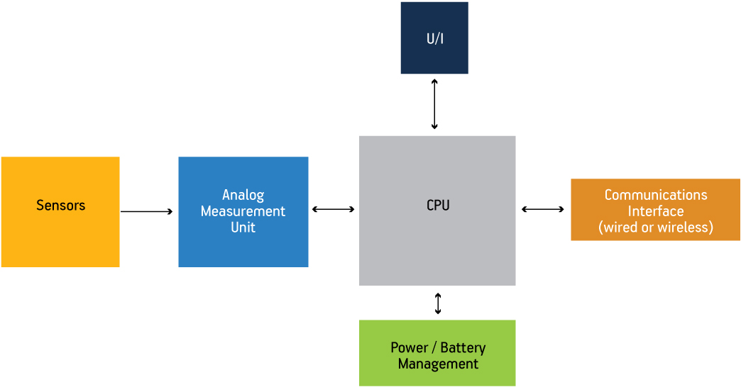
Figure 1
Block diagram of a portable medical device
Source: Freescale Semiconductor
- mixed-signal integration;
- low-power performance;
- display technology; and
- connectivity.
Technology providers, like Freescale Semiconductor, are delivering key advances in these strategic areas to enable medical market customers to optimize their products.
Mixed-signal integration
The ability to analyze a very small data signal captured by a sensor is fundamental to almost any medical device design. To perform this analysis, designers should be considering the integration of microcontrollers (MCUs) with integrated op-amps, with a high-resolution analog-to-digital converter (ADC), a digital-to-analog converter (DAC), an analog comparator (ACMP), and a voltage reference (VREF).
In the example of a blood glucose monitor, the signal is the electrochemical reaction initiated by a glucose measurement. The first stage of the blood glucose analysis involves identifying the peak of the biosensor’s electrical output. The integrated op-amps are used to amplify and filter the signal, and the analog comparator (ACMP) peripheral can be configured to trigger an interrupt once the peak has been reached. The next stage requires precisely timed analog-to-digital conversions of the glucose meter strip’s linearly decaying output. Device designers should be looking for a feature-rich 12bit or 16bit ADC that enables these measurements. The ADC should have automatic compare and flexible conversion time settings, the ideal for this type of analysis. Finally, the CPU (8bit or 32bit) is used for the mathematical portion of the analysis.
Though analog circuits can be utilized on or off a chip, on-chip integration of analog functionality provides many system cost benefits. The obvious one is that it reduces the need for external ICs, thus reducing the bill of materials and board footprint. Beyond that, on-chip analog also features low-voltage detection and internal bandgap reference voltages, which lower overall cost further.
Ultra-low-power platform
Ultra-low-power performance is important to portable medical products for many reasons, although the most significant is battery life. Device designers need to evaluate the MCUs vendors offer that utilize innovative technology to achieve the absolute lowest power. For example, each of the devices within Freescale’s ultra-low-power product portfolio contains four main features that are the foundation of low-power operation.
- A low-power crystal oscillator
- Low-power modes of operation
- A flexible clock source
- Connectivity
Low-power crystal oscillator
The crystal oscillator used in the Freescale devices has been optimized for driving crystals at low power with options for low- or high-gain modes. It consumes less than 500nA for a 32.768kHz crystal in low-power modes. It allows accurate time to be kept while the MCU is in a standby power mode (Stop mode). This is important because it can significantly increase battery life.
Low-power modes of operation
Figure 2 shows the multiple modes of operation in Freescale’s energy-efficient MCUs. Each is tailored to a specific level of functionality to allow the most efficient performance/power consumption tradeoffs. The modes support power consumption as low as 250nA for some devices and enable medical applications to continuously operate with the highest energy efficiency. The modes also enable many MCU peripherals to operate in low-power run mode to provide the right functionality mix in a low-power mode.
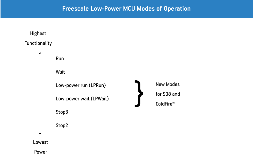
Figure 2
Freescale low-power MCU: modes of operation
Source: Freescale Semiconductor
Flexible clock source
Related to the benefits provided by the operating modes, the internal clock (ICS) peripheral on the energy-efficient MCUs provides an ability to ramp up or down a device’s operating frequency. Higher operating frequencies lead to higher run mode power consumption. Depending on an application’s requirements, running at a lower operating frequency will allow the power to be reduced by about 500µA per MHz. The ICS will allow the embedded developer to fine-tune the MCU’s performance to optimize power consumption.
To further reduce run mode power consumption, each peripheral on the low-power platform can be clock gated. This is a way of shutting down the clock signal that is routed to a peripheral. Clock gating a single peripheral only reduces power consumption by tens of microamps, so when reaching for the lowest consumption possible, you must reduce every unneeded internal trace and clock signal. When clocks to all peripherals are disabled, clock gating has been measured to reduce run mode power consumption by almost one third.
Utilized together, the features described in the previous section can optimize a portable medical design, for more energy-efficient operation.
Display capabilities
Portable medical devices have adopted many different display technologies, ranging from low-power, low-cost LCDs to more aesthetically pleasing SVGA screens. Cost is the main criterion for most portable medical device designers, so LCDs currently dominate. When choosing an MCU with an integrated segment LCD controller, the following features should be considered.
First, you will need an ability to assign front plane (segment) or backplane (common) functionality on any of the MCU’s pins. With this feature, signal layout can be optimized so that PCB board space can be minimized. This feature also allows different LCD glass designs to be more easily switched in and out of the system because the hardware change can be handled by a software update. One example of a flexible LCD driver is described in the Freescale application note, LCD Driver Specification, which can be downloaded as a PDF from www.freescale.com (document number AN3796).
Second, you want to drive more display segments with fewer pins. This means that more pins can be used for general-purpose I/O (GPIO) ports. Freescale utilizes x8 mixing of the LCD signals so it only takes 28 pins (8 x 20) to drive 160 LCD segments. The same functionality requires 44 pins on many MCUs. By using fewer pins, board size and connector space are reduced, enabling more compact portable medical designs.
Finally, the LCD peripheral architecture should be designed to provide the most energy-efficient performance. Freescale’s MC9S08LL16 products have total system power as low as 1.5µA with LCD glass connected. This performance, along with a low-power blinking mode (the ability to blink the display while in stop mode), allows product developers to lower average power consumption by up to 70% for portable medical designs. This lengthens battery life and further reduces the cost of the battery types used in the end device.
Making connections
The ability to transfer information from a portable medical device to a PC for analysis or the creation of an electronic medical record (EMR) is another important option that must be considered for new portable medical device designs.
USB
Standard serial peripherals, such as SPI, SCI and I2C, are essential for providing basic connectivity that allows data transfers within systems, but USB has recently become the most common and widely used wired protocol for communication between a portable medical device and a PC. The main reason USB has become so prevalent is that it is the first of the wired communication protocols to become a standard of the Continua Health Alliance, a consortium of more than 200 member companies from the technology and the medical device markets focused on developing a standard system of connected personal medical solutions.
Three main factors need to be considered while selecting a particular USB connectivity software implementation for medical devices.
- Standardization: The product should be based on well-known, well-supported standards in the industry. This will ensure success and proper introduction of the product to the market.
- Connectivity: The implementation should allow for the connection of multiple devices from different vendors within an ecosystem topology. A connectivity-friendly environment is sustained by a robust and easy-to-use software stack.
- Portability: A multi-device, independent-layered architecture eases the porting of code between devices. Selecting a hardware vendor with a broad portfolio is key to ensuring customization and product roadmap establishment.
The software architecture ensures code robustness portability and reliability in embedded systems development. An architectural diagram of the USB personal healthcare device (PHDC) stack is shown in Figure 3. Several layers of software abstraction isolate the reference application from the low-level communication drivers, permitting code-reuse and portability between devices. The portability, high data rate and standardized ecosystem make the USB PHDC stack a perfect fit for portable medical applications. Freescale offers the stack free-of-charge for use on any of its MCUs (you can download a copy at <a href="http://www.freescale.com/medicalusb“>http://www.freescale.com/medicalusb).
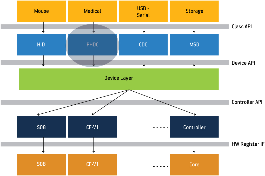
Figure 3
Block diagram of a USB stack with PHDC support
Source: Freescale Semiconductor
ZigBee
Medical device designers have a wide variety of options when it comes to choosing a wireless protocol. A list of those that Continua is investigating is shown in Figure 4.
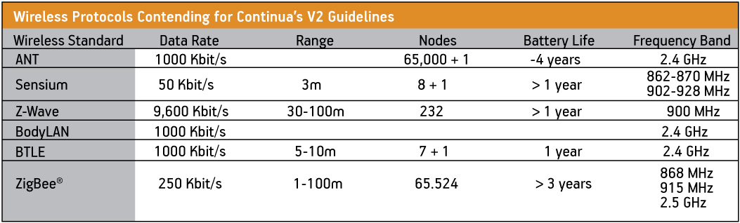
Figure 4
Wireless protocols contending for inclusion in Continua v2
Source: Freescale Semiconductor
In April 2009, the wireless technology ZigBee became the first communication standard certified by Continua’s V2 guidelines. ZigBee is specified for short-range, low-energy applications where only short bursts of data are required (i.e., non-streaming data). Its low latency and sleep modes allow ZigBee to boast low power consumption characteristics. Furthermore, based on the simple ZigBee framework, processor memory and performance requirements are low. The combination of low data rate, low power consumption and small memory footprint make ZigBee the ideal choice for a portable medical device design.
References
- Garcia, Donnie et. al., “Gestational Diabetes: Technology can help reduce complications”, Beyond Bits IV: Health and Safety, Summer 2009.
- Sharma, Raman, “Low-Energy Wireless: Just what the doctor ordered”, Beyond Bits IV: Health and Safety, Summer 2009.
Freescale Semiconductor
6501 William Cannon Drive West
Austin
TX 78735
U.S.A.
T: +1 800 521 6274
W: www.freescale.com/medical.