USB Type-C: Verification challenges and solutions
The USB Type-C connector is versatile and already gaining traction in laptops, tablets and desktops. Here’s how verification IP plays an important role in achieving the best implementation.
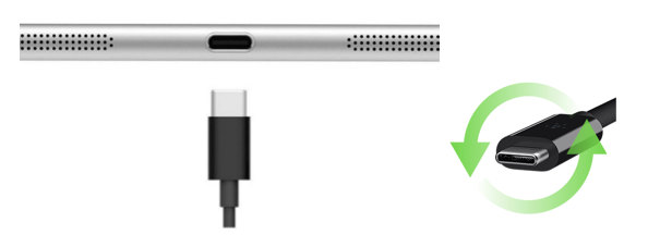
The USB connector that we are all most familiar with is Type-A. Even as the USB data interface evolved from USB1 to USB2 and then to USB3, it remained the same. It is a massive connector that can be inserted in only one orientation.
These limitations are resolved by the USB Type-C connector. In addition to flexibility and small size, the Type-C connector handles the greater power requirements of today’s USB ports. It also supports a variety of different protocols using ‘alternate modes’: These enable the use of adapters that can output HDMI, VGA, Display Port, or other types of connection from a single USB port.
The main advantages of a USB Type-C connector are:
- It transports up to 100W of power.
- It removes user confusion about plug orientation.
- It supports legacy USB standards such as USB2.0, USB3.1, and USB Power Delivery (PD).
- It provides alternate-mode support for standards like HDMI, VGA, Display Port, etc.
For these reasons, the USB Type-C connector is expected to replace existing USB, power, and display related connectors on tablets, laptops, and desktops.
This paper describes the challenges faced in the verification of USB Type-C connectors and of USB Type-C connectors integrated with USB PD. It provides insights into how Mentor Graphics’ Questa Verification IP (QVIP) with mixed-signal SystemVerilog constructs helps overcome these challenges.
Introduction of USB Type-C
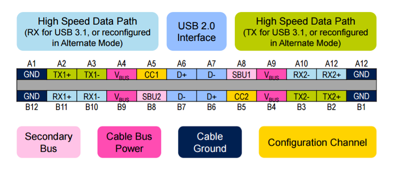
USB Type-C is a 24-pin reversible-plug connector for USB devices and USB cabling. Type-C connectors connect to both hosts and devices, replacing various Type-A and Type-B connectors.
This double-sided connector provides pins for super-speed data, high-speed data, cable orientation detection, and dedicated BMC configuration data channels for USB PD communications. Connecting an older device to a host with a Type-C receptacle requires a cable, or an adapter with a Type-A or Type-B plug, or a receptacle on one end and a Type-C plug on the other.
While the Type-C interconnect no longer physically differentiates plugs on a cable as being either an A-type or B-type, the USB interface maintains a host-to-device logical relationship.
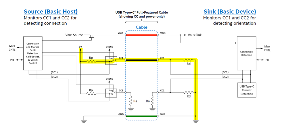
The standard concept for setting up a valid connection between a source and a sink is based on being able to detect terminations residing in the product being attached. USB Type-C involves cable orientation detection and establishment of the power roles (source-sink) and data roles (host-device). Both of these require monitoring of the voltage (V), resistance (R), and current (I) values on the configuration channel (CC) pins of the connector.
With the Type-C connector, a source may implement higher source current to enable faster charging of mobile devices. The USB host and hubs advertise the level of current presently available via the CC pins. Three current levels are defined by the USB Type-C standard at the default VBUS:
- Default values, as defined by a USB standard
(500mA for USB2.0 ports, 900mA for USB3.1 ports) - 5A
- 0A
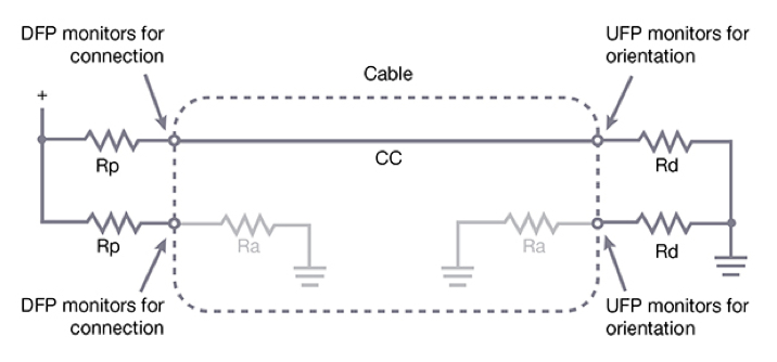
Figure 3: USB Type-C source/sink roles are established with pull-up (Rp) and pull-down (Rd) resistors
Initially, a source exposes independent pull-up (Rp) terminations on its CC1 and CC2 pins, and a sink exposes independent pull-down (Rd) terminations on its CC1 and CC2 pins. The source-to-sink combination of this circuit configuration represents a valid connection. Once the sink is powered, the sink monitors CC1 and CC2 for a voltage greater than its local ground. The CC pin that is at a higher voltage (i.e., pulled up by Rp in the source) indicates the orientation of the plug, and a valid connection is established.
USB Type-C verification challenges
The key challenges faced in the verification of USB Type-C designs and their integration with USB PD have to do with these features:
- Establishment of the initial power (source-to-sink) relationship using the two (CC1 and CC2) pins on the USB Type-C receptacle.
- Establishment of the initial data (host-to-device) relationship using the two (CC1 and CC2) pins on the USB Type-C receptacle.
- Plug orientation and cable twist detection:
- Unflipped straight-through connection (CC1 with CC1)
- Flipped straight-though connection (CC2 with CC2)
- Unflipped twisted-through connection (CC1 with CC2)
- Flipped twisted-through connection (CC2 with CC1)
- Collision resolution:
- This is required when both the ports try to act as source (or sink). In this case, the collision needs to be resolved by making sure that one of the two ports backs out and decides to take up the other role, so that a source-sink connection can be established.
- USB Type-C VBUS current range detection:
- Default value (500 mA for USB2 and 900mA for USB3.1)
- 5A
- 0A
- USB PD communication:
- The USB PD Bi-phase Mark Coded (BMC) communications are carried on the CC wire of the USB Type-C cable.
- Set up and manage power and accessory modes.
- Dynamic detach detection and re-attach:
- In this scenario, the source monitors the attached CC pin and the sink monitors the VBUS to detect detach.
- VCONN detection:
- Since only a single CC pin position (either CC1 or CC2) within each plug of the cable is connected through the cable, the other CC pin that is not connected through the standard cable is repurposed to the source Vconn to supply power to the local plug. Initially, the source supplies Vconn and the source of Vconn can be swapped using USB PD VconnSwap.
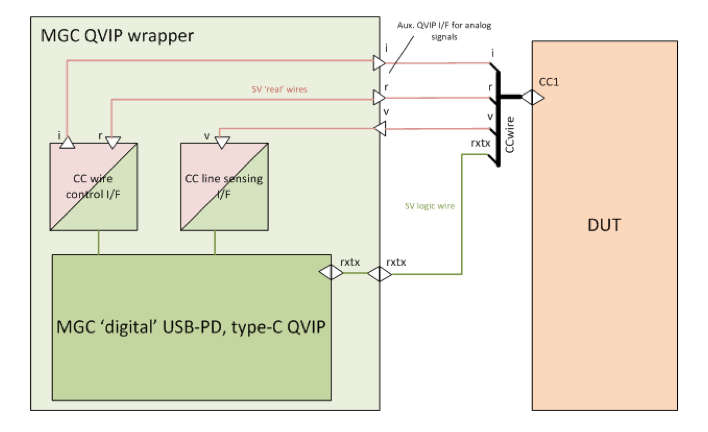
All these features need to be verified thoroughly to make sure that a USB Type-C design works properly. This requires constant monitoring and resolution of the current (I), resistance (Rp, Rd, and Ra), and voltage (V) values on the CC1 and CC2 pins of the receptacle. So, the verification IP must be capable of performing mixed-signal simulations. Since the USB PD communication also happens on the connected CC pin, the verification IP must also provide a seamless method of integrating USB Type-C interfaces with USB PD interfaces.
Questa Verification IP for USB Type-C
Using the latest constructs of SystemVerilog mixed signal modelling, Questa Verification IP (QVIP) aims to provide a user-friendly solution to the USB Type-C verification challenges and the integration of USB Type-C with USB PD. QVIP also provides a ready-to-use test suite (along with functional coverage) for both USB Type-C and USB PD, enabling complete verification of USB Type-C and USB PD features.
These are the main features provided by QVIP.
- Source-sink detection and dynamic power role switching:
- QVIP provides flexibility to configure the initial power role of the QVIP and starts advertising/monitoring current and voltage accordingly. Once the roles are decided based on the resultant voltage on the CC pins, QVIP also provides flexibility to switch the power roles (source-to-sink and vice-versa) dynamically.
- Host-device detection and dynamic data role switching:
- QVIP provides flexibility to configure the initial data role of the QVIP, and once the power connection is established, the QVIP starts operating in the configured role. QVIP also provides flexibility to switch the data roles (host-to-device and vice-versa) dynamically.
- Plug orientation and twisted cable detection:
- Using mixed signalling constructs of SystemVerilog, the QVIP is able to detect the USB Type-C plug orientation and establish the connection accordingly. QVIP also provides flexibility of straight and twisted cable connections.
- Collision resolution:
- Based on the current and resistance values advertised by the two ports on the CC1 and CC2 pins, it is possible that the resolution might not happen if both ports want to operate as source (and similarly if both ports want to operate as sink). In this case, QVIP provides collision resolution by switching its role and drives the CC1/CC2 pins according to the switched role.
- USB PD communication:
- QVIP provides a seamless integration of USB Type-C with USB PD. Once the USB Type-C connection has been established, the USB PD communications are enabled.
- Accessory modes support:
- QVIP supports all types of accessories (audio, debug, and powered). QVIP can also be configured to operate as one of the accessories.
- Dynamic detach:
- While the USB PD communications are in progress, it is possible that the USB Type-C connection might get lost, due to the absence of VBUS or a change in current. QVIP is able to handle these situations, and it also provides flexibility to switch roles during re-attach.
- Error injection:
- QVIP provides support for different types of error injection in the USB Type-C signaling and USB PD communications.
- Data recovery:
- The USB PD standard defines the unit interval in the range of 3.03 µs to 3.70 µs, which means that the bit width of the data transmitted can lie in this range. QVIP is capable of receiving the data sent at any frequency within this range. QVIP also provides configuration to generate the data at varying frequencies.
- QVIP as policy engine:
- QVIP can be configured to operate as the policy engine where the CC line will not be driven by QVIP. Instead the QVIP will provide instructions to the PHY DUT about the packets to be transmitted and will take appropriate actions after receiving any packet.
- Sequence library:
- QVIP provides an exhaustive test plan to verify the DUT. More than 150 sequences are provided in the test plan. Each sequence provides the option for randomization of various fields and an error injection capability.
- Functional coverage:
- QVIP provides functional coverage for both USB PD and USB Type-C to ensure that all corner cases get covered. Certain modes of USB Type-C coverage can also be switched off based on the DUT supported configuration.
- Scoreboarding:
- Data integrity checks are performed on the USB PD data transfers.
- Ease of debugging:
- QVIP provides various debug options to make the debugging easier, which includes a transaction logger, USB Type-C signals in waveform, and protocol assertions.
Conclusion
“The Type-C plug is a big step forward,” says Jeff Ravencraft, chairman of the USB Implementers Forum (USB-IF), the organization that oversees the USB standard. “It might be confusing at first during the transition, but the Type-C plug could greatly simplify things over time by consolidating and replacing the larger USB connectors.”
Questa Verification IP provides an easy and user friendly solution for the verification of USB Type-C and USB PD features. QVIP provides a solution to the mixed signal verification challenges involved with USB Type-C signaling. The comprehensive sequence library reduces the stimulus generation time, and easy debug components reduce debugging and verification time.
To learn more about QVIP, you can visit several whitepapers on mentor.com, including Verifying Display Standards – A comprehensive UVM based Verification IP Solution and Verification IP Stimulus APIs – Are They Really Easy to Use?
