Symbolic simulation speeds timing closure
Timing closure is a key challenge for today’s complex system-on-chip designs. Static timing analysis (STA) tools automatically analyze signal paths in a design and identify timing-critical paths that limit the clock frequency that can be achieved. Paths that can never be functionally activated or that require multiple cycles for correct operation can be identified as critical paths by STA tools. To improve the quality of results achievable by physical synthesis tools, such exceptions to timing need to be specified as design constraints. Generating these constraints is an error-prone and time-consuming process so automation is clearly required. The article describes how taking a symbolic simulation approach to the automatic generation of timing constraints significantly speeds up timing closure.
Timing closure and power management continue to be key challenges for system-on-chip (SoC) designs. As design complexity increases—chips fabricated on advanced processing nodes from 28nm downward already contain more than 100 million gates. Those challenges will only increase. Effective power management often requires dozens of different clock domains. Successfully implementing these seems to require more and more design iterations, driving up NREs.
Logic synthesis, static timing analysis (STA) and place-and-route (P&R) tools can improve the quality of results (QoR) when infused with design constraints that include robust timing exceptions. These exceptions are paths that are either false paths (FPs) (perhaps because of conflicting requirements for path activation because of multiple modes in the design) or multi-cycle paths (MCPs) (requiring multiple cycles for correct operation). Constraints are typically provided in a vendor-specific design constraint file format.
Manually writing a design constraint file is time-consuming, error-prone and iterative. Instead, an automated technique using symbolic simulation can be used to create a constraint file that improves timing closure, with reduced engineering effort.
RTL to layout flow
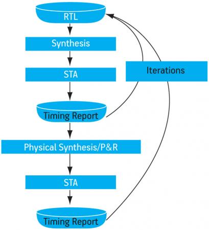
Register transfer level (RTL) designers today use a flow similar to that in Figure 1. It starts with RTL coding, followed by logic synthesis and STA. The designer reads the resulting timing report to identify paths with negative slack that fail to meet timing, and then devises and writes timing exceptions by hand. Another loop is necessary after physical synthesis, P&R and STA. When a design has thousands of paths with negative slack, this approach creates a bottleneck that is so risky and takes so long to traverse that it is neither feasible nor reliable.
Figure 1
Traditional design flow results in multiple iterations
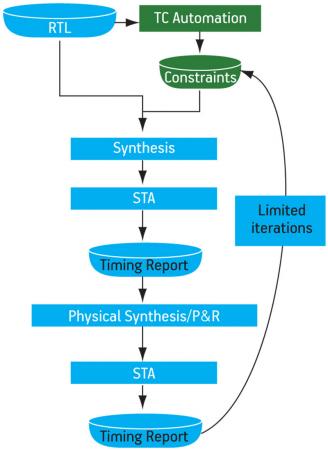
Eliminating this bottleneck requires greater automation. We can improve the QoR and accelerate timing closure, with fewer iterations by automatically generating a design constraint file that is robust, complete and quick to run (Figure 2).
Figure 2
Automatically generating timing constraints speeds closure
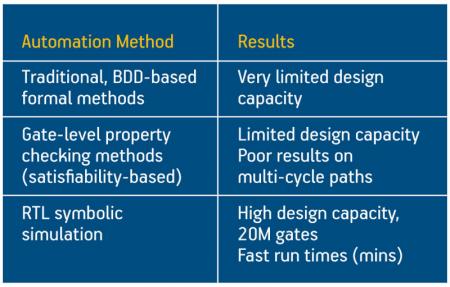
Several formal verification-based approaches to automate design constraint file generation have been tried already (Figure 3). However, traditional formal and gate-level property checking methods are inefficient. They are limited to small blocks, and often produce poor results on multi-cycle paths.
Figure 3
Candidate methods for automatic design constraint file generation
Having few options, designers have typically relied on a manual approach to constraining the design. But this is far from satisfactory. For example, a designer may use a wild card to rapidly code exceptions, inadvertently matching design elements that the designer did not intend to include in the set of false and multi-cycle paths. Furthermore, designers may not consider all the behavior that determines false or multi-cycle path operation, missing critical constraints that could have a substantial impact on timing, power, or area. Even worse, designers can miss control behavior that invalidates specified exceptions, and the incorrectly specified constraints can result in the need for a re-spin.
RTL symbolic simulation is a new approach that shows promise in implementing a predictable, reliable method of generating timing constraints in multi-million gate designs on run times of minutes to hours.
Symbolic simulation
Standard logic simulation uses discrete values such as 0, 1, Z and X to represent logic states, while symbolic simulation uses symbols for inputs such as DATA or ADDRESS and then propagates manipulated symbols to the outputs. Symbolic simulation has traditionally been used at the gate level and has suffered from memory explosion because of its reliance on binary decision diagrams (BDDs). Recently, symbolic simulation approaches that overcome the previous limitations of gate-level approaches by performing simulation at the RTL have been proposed [1].
Blue Pearl Software offers tools that use symbolic simulation for RTL designs to analyze and automatically generate a set of functional false and multi-cycle paths. Each path is found by a functional analysis of the behavior in the control logic. A major difference between symbolic simulation and logic simulation is that symbols are used instead of logic states to exhaustively simulate the behavior of the design without requiring test stimuli.
Blue Pearl’s Cobalt Timing Constraint Generation tool employs symbolic simulation to analyze behavior at a higher level of abstraction than traditional logic-level approaches. It determines design intent by working at the level of finite state machines (FSMs), sequentially controlled data paths and counters. Cobalt can explore a large design space to comprehensively analyze paths, and generate a safe and effective set of timing constraints.
By rapidly analyzing sequential control behavior, Cobalt generates complex functional false and multi-cycle paths that would be very time-consuming or even impossible to identify manually.
False and multi-cycle paths
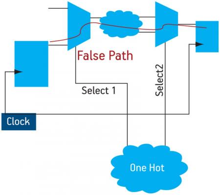
The logic diagram in Figure 4 (p. 31) has a path highlighted that passes through two multiplexers and a cloud of logic. However, the two select lines (‘Select1’ and ‘Select2’) never go active at the same time because they are controlled by one hot logic. This path is an example of a false path that cannot logically occur. Symbolic simulation identifies this as a false path in the design constraint file.
Figure 4
Symbolic simulation identifies false paths
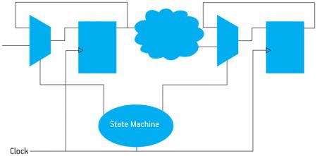
An example of a multi-cycle path is shown in Figure 5. Symbolic simulation identifies the FSM and how it controls a multi-cycle path through the flip-flop on the left, a cloud of logic in the middle, and the flip-flop on the right. For example, if the FSM can launch a transition at the start point of the path only in state ‘Sn’, can capture the transition at the end point of the path only in state ‘Sm’, and there are always a minimum of three cycles between ‘Sn’ and ‘Sm’, then a multi-cycle path will be reported.
Figure 5
Symbolic simulation analyzes multi-cycle paths
Design example: end point slack distribution
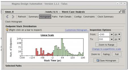
To illustrate the effects of automatically generated timing constraints on timing metrics, let’s look at a logic design block that was run through the Magma Talus physical synthesis tools with only clock timing constraints. The Magma CPU runtime was 11.8 minutes. The resulting histogram report shows the slack time distribution (Figure 6). Green is positive slack and red is negative slack. As can be seen, there is a lot of red. The worst-case path slack was -106ps, total negative slack was -22,580ps and there were 346 failing end points. To manually analyze each of the paths that failed to meet timing and then handwrite a design constraint file specifying timing exceptions would take weeks.
Figure 6
Talus histogram shows path slack time
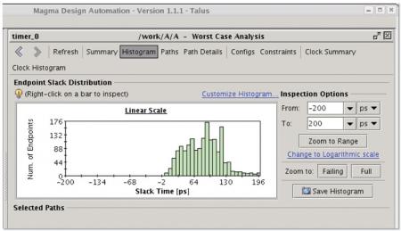
The same logic design block was then run through the Cobalt tool, which generated a design constraint file containing approximately 500 timing exceptions within a few minutes. It was then run through the Magma tools again (Figure 7). When Cobalt generated constraints were used, the resulting timing histogram showed all timing paths had positive slack because the target timing had been met. The Magma CPU runtime was 11.5 minutes, the worst-case path slack was +5ps, the total negative slack was 0ps, and there were 0 failing end points.
Figure 7
Talus histogram after running the Cobalt tool
The Blue Pearl tools focus on the true logic paths and not the false and multi-cycle paths. This results in area and power reductions because the logic and physical synthesis tools can avoid resizing cells and adding extra buffers.
Trusting the design constraint file results
Automatically generating a design constraint file sounds like a wonderful timesaver, but how does one really know that the timing constraints are correct?
The Cobalt tool creates System Verilog Assertions (SVA) or Property Specification Language (PSL) assertions for every timing exception in the design constraint file, giving designers the ability to validate the results using functional simulation or formal property checking tools. When you run logic simulation or formal property checking, an incorrect timing exception triggers the related assertion and indicates that there is an issue with the path constraint.
Blue Pearl’s False Path Audit Trail automatically identifies the logical conflicts that prevent path activation and produces a constraint origination report. When used with SpringSoft’s Verdi schematic tool, it allows one to trace paths visually, instead of browsing an RTL text file. This gives designers the added reassurance of the validity of automatically generated constraints by helping them easily understand the reasons why the paths in their design are false.
References
1. “Symbolic RTL simulation”, A. Kolbe et al., Proc. Design Automation Conference, 2001, pp. 47 – 52
Blue Pearl Software
4677 Old Ironsides Drive
Suite 430
Santa Clara
CA 95054
USA
T: +1 408 961 0121
W: www.bluepearlsoftware.com
