Signoff-driven IC design
The demands of manufacturing closure at advanced process nodes make the traditional design-then-fix flow unmanageable. At 28nm and below, designers need a solution that can address manufacturing issues at any point in the design process, enabling a true correct-by-construction methodology. An effective solution must provide design-rule-check and design-for-manufacturing analysis using the actual foundry-approved signoff rules and engines, integrated directly with the place and route system. It must also provide automated repair and re-verification to ensure that all fixes are signoff clean without lengthy and non-convergent manual fixing. Finally, the router must be able to optimize for timing, power, signal integrity and die size at the same time as it is observing manufacturing constraints. This requires concurrent MCMM capability that can handle an unlimited number of scenarios within the router, in addition to tight integration with the signoff checking engines. Such an integrated design and verification solution is described in the following article. It is our contention that this strategy eliminates the traditional design-then-fix iterations required today, cuts time-to-manufacturing-signoff and reduces overall development costs and effort. Using a signoff-driven design approach, the traditional manufacturing closure process that typically takes weeks or months can be reduced to days.
Until the 40nm node, there was continued debate about the need for design for manufacturing (DFM). But things have changed. As we move into sub-40nm designs, manufacturing closure—i.e., closing a design for all manufacturing requirements, in addition to traditional performance parameters—is becoming a major bottleneck. The traditional tools and methods used to complete a physical IC design and make it ready for manufacturing signoff no longer work, and new approaches are needed. The old two-step process—design it, then fix it—is giving way to integrated design and manufacturing closure, where complex design-rule-check (DRC) and DFM issues are addressed as the layout is created.
Why manufacturing closure is now so difficult
Why don’t traditional design flows work below 40nm? While all the main sources of difficulty relate to continuously shrinking dimensions in a manufacturing environment facing fundamental physical limitations, it does help to break things down a little further to see various aspects of the problem.
First, production steppers have been using 193nm light sources since the 90nm node, and with exposure wavelength now more than five times larger than the critical dimensions being imaged at the 28nm node, optical systems simply cannot render such small shapes with enough resolution. Straight layout edges are no longer straight edges on the die. Gates are shortened or distorted, and interconnects can become pinched. Lithography effects are complicated by limitations in etching. Layout density affects planarity during the CMP process. That in turn affects the accuracy of the exposure focus and can lead to other issues such as copper pooling, which can cause shorts. Due to all these complexities at advanced nodes, the defect rate is no longer dictated by random particle effects; instead, systematic failure mechanisms start to dominate.
To maintain yield, IDMs and foundries are being forced to tighten up their design rules so that physical features susceptible to these effects are not introduced into the design. They are also making model-based DFM analysis mandatory, and this makes designers more responsible for ensuring that a design not only meets performance, power and cost targets, but also that it is manufacturable.
The reality of these changes is hitting designers in the form of exponentially increasing sets of DRC and DFM checks that must be passed to achieve manufacturing signoff (Figure 1). The number of DRC and DFM rules has roughly doubled between the 90nm and 32nm nodes, depending on the foundry. Rule complexity—measured by the number of operations required to verify a rule—has grown even faster, more than doubling since 90nm. Ignoring the new rules can lead to problems ranging from chip failure to reduced reliability.
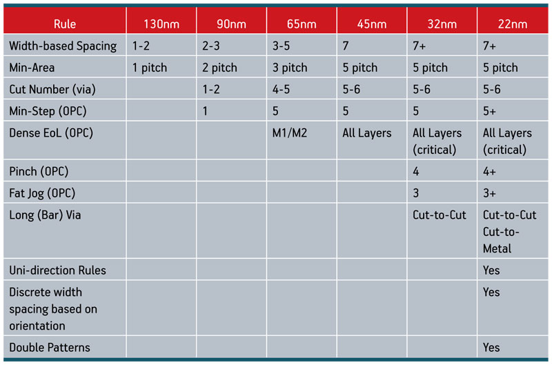
Figure 1
Below 40nm, foundries must set many design rules and make DFM analysis mandatory
However, changes to improve manufacturability can also reduce performance, increase power consumption, and otherwise compromise the design. Designers must be able to make smart tradeoffs when fixing DRC/DFM violations to ensure high yield without over-designing and sacrificing performance. Unfortunately, the current design-then-fix strategy is not adequate to address these new challenges for a number of reasons.
Design-then-fix doesn’t work anymore
The traditional flow consists of completing the physical design and following that with physical verification checks and DFM improvements. It is based on the assumption that the place-and-route (P&R) tool can get ‘close enough’ to the desired outcome that the fixing process is manageable. In the past, this assumption held good, but it begins to break down below 40nm. There are so many new, complex rules that existing routers simply cannot deal with all the constraints (Figure 2).
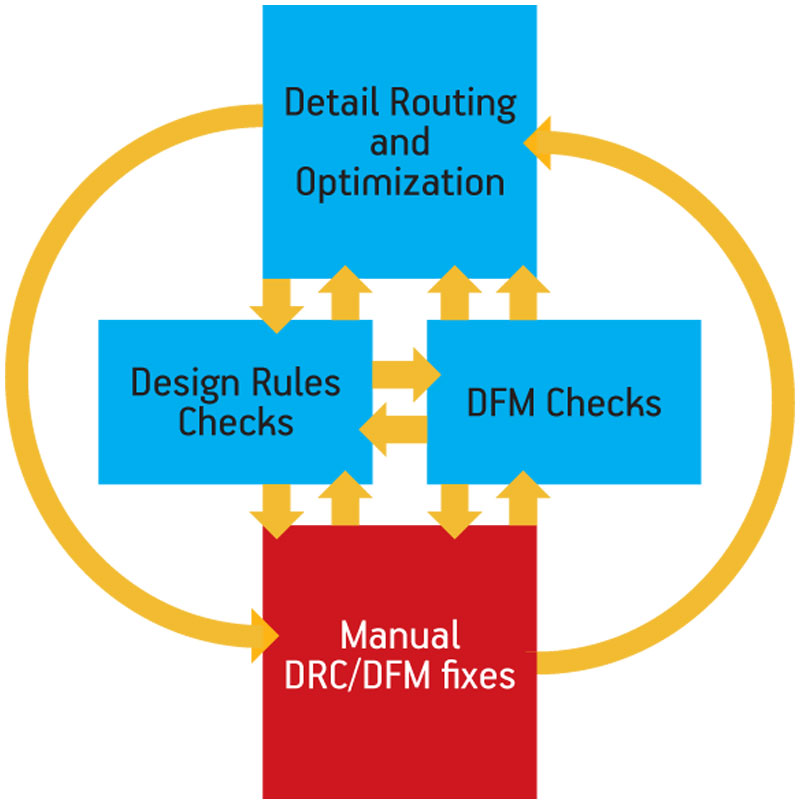
Figure 2
The traditional design-then-fix methodology breaks down at advanced nodes
Most routing algorithms are based on closing only a few scenarios (design corners) at a time, and use simplified DRC/DFM models during initial routing. Only during final routing (aka the ‘search-and-repair’ phase) does the router switch to more complete DRC/DFM models where violations are fixed in a post-route loop. For previous nodes, this approach worked adequately because the number of violations remaining after initial routing was typically in the region of tens-to-hundreds. In addition, the changes made to repair violations did not significantly affect timing, power, signal integrity (SI), and other performance factors.
However at 40nm and below, the number of violations has exploded into the thousands for the reasons discussed above. In this scenario the search-and-repair methodology becomes problematic because the design is mostly completed and ‘locked in’. There are just too many issues to fix.
Also, any changes made at this point can have ripple effects, leading to new manufacturing violations, or negatively impacting the performance targets of the design. For example, adding metal fill to improve planarity, or moving wire edges to remove a pinching condition can cause degradation to timing and SI as parasitic interactions change. Unable to close all the design corners and manufacturing constraints simultaneously, the designer falls into a lengthy and non-convergent ECO loop. Obviously, if the router cannot handle this level of complexity, manual fixes are not going to fare any better.
Another problem is a growing disconnect between design and verification rules. As a process node matures, the foundry’s design rule files, expressed in the Standard Verification Rule Format (SVRF) language, are constantly updated to address manufacturing issues as they are discovered. Consequently, these foundry signoff models are intrinsically the most accurate and complete representation of actual manufacturing requirements. However, the rules used by the P&R system, expressed in the Library Exchange Format (LEF) syntax, are simpler and frequently fall behind the SVRF rules (in fact, at 28nm and below, there are some rules described in SVRF that simply cannot be expressed in the simpler LEF language).
As a result, during design the router may report the layout to be DRC/DFM-clean, but the signoff physical verification tool will later uncover a large number of violations. Even subtle mismatches can cause an unmanageable number of violations late in the design cycle, leading to time-consuming iterations between design and verification environments to fix them. Unfortunately, the gap between design and verification models is increasing, resulting in a growing number of late-stage surprises at signoff.
All these challenges are exacerbated by the fact that there is usually no automated way to make the DRC/DFM repairs. In the past, a handful of violations could be fixed manually without affecting the design too much. But when you have thousands of violations, manual fixing is not feasible.
Finally, a traditional flow is characterized by huge and lengthy ASCII file transfers between the implementation and signoff environments for each iteration. As design sizes increase, a flow based on ASCII file transfers cannot scale and becomes a big time sink in an already painful closure process.
How to address new challenges
This is a pretty scary list of problems to confront while you are also trying to handle the complexity inherent in multi-million gate designs. Is there any help available?
One response to these manufacturing closure challenges replaces design-then-fix with a correct-by-construction methodology (Figure 3). This moves manufacturing closure actions early enough in the design process to allow them to be effective, to avoid late stage surprises and to avoid ripple effects leading to non-convergence iterations. An effective manufacturing closure solution must have these basic capabilities.
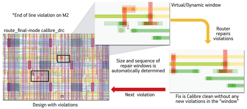
Figure 3
Signoff-driven automatic prevention and repair
- DRC and DFM analysis during design using the same rules and engines employed for final signoff, so that decisions made during routing will actually meet manufacturing closure requirements.
- Automatic fixing and incremental verification of DRC/DFM violations at either the block or full chip level, whenever the designer decides to check for manufacturing closure.
- Routing technology that can optimize for a virtually unlimited number of scenarios so information provided by the DRC/DFM analysis can be used to concurrently optimize the layout for all timing, power, SI and manufacturing issues.
These capabilities describe a system that integrates physical design, verification and DFM operations into a single platform that allows manufacturing issues to be identified and automatically fixed concurrently with the design process. Not only are the manufacturing issues addressed earlier in the design process, but the tradeoffs between timing, power, SI and manufacturability are considered simultaneously in order to achieve a design that is truly optimized and meets all performance and manufacturing requirements.
A working example
To get a better idea of how the new approach works in practice, let’s compare the traditional design-then-fix methodology to an integrated manufacturing closure approach provided by the Calibre InRoute design and verification platform from Mentor Graphics (Figure 4).
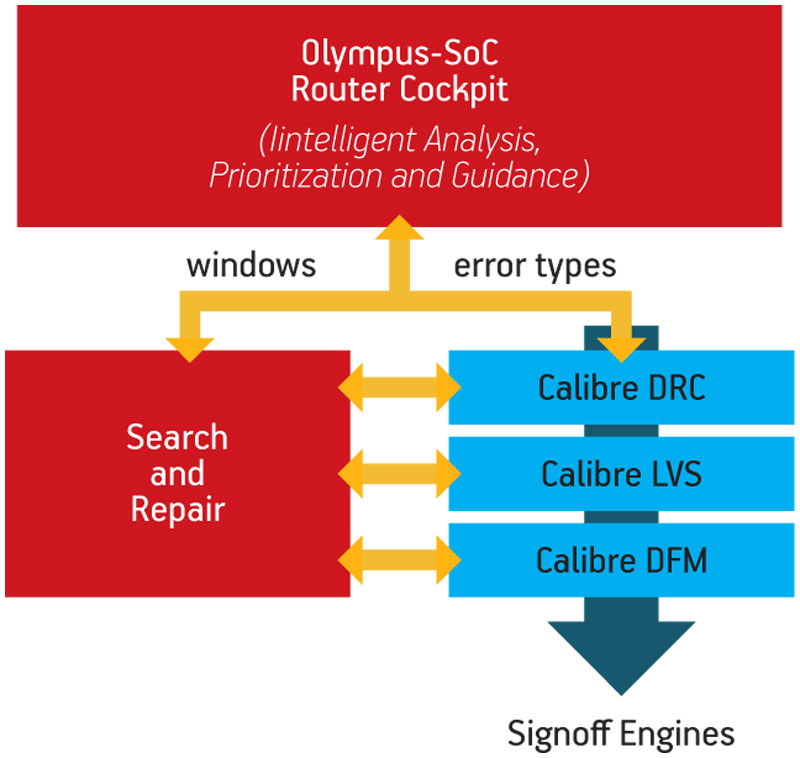
Figure 4
The Calibre InRoute platform makes it possible to drive manufacturing closure concurrently with physical design
Using the conventional approach, a design is first placed and routed. The P&R tool uses heuristic algorithms to avoid as many DRC and DFM violations as possible during initial routing. It then goes into a ‘search-and-repair’ phase using its own DRC and DFM checkers to remove any remaining violations. When completed, the design appears to be free of DRC/DFM violations. However, once analyzed with Calibre for manufacturing signoff, nearly 1,500 violations are uncovered resulting from a complex end-of-line rule that was not addressed by the P&R tool (Figure 5). The violation is caused by incorrect spacing from the adjacent via pad. It was not found by the DRC checker during P&R because the technology file was outdated.
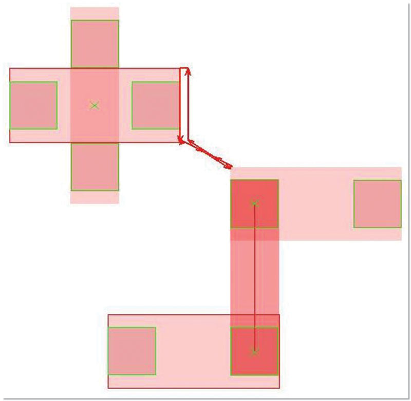
Figure 5
End of line rule violation found only during signoff verification
The 1,500 violations are annotated back into a layout editing environment and a designer fixes the violations manually, referring to the foundry design rule manual to understand the cause of each violation. After all the layout changes are made, new timing, SI and power verification analysis must be run to ensure that the performance specifications of the design have not been degraded too much. Then another signoff check must be run to verify that all the violations have been fixed. Although the original end-of-line violations are fixed after these lengthy and laborious efforts, the layout changes unfortunately introduce new violations that require additional iterations through the fix-then-verify loop. The changes also have unintended impacts on a critical clock path, so although within specification, the overall design is no longer fully optimized.
In contrast to the design-then-fix approach, an integrated design and verification platform allows designers to natively invoke SVRF rule decks and tools within the P&R system to achieve manufacturing closure directly as the physical design proceeds. Because checking is easy and fixing is automatic, the designer can address manufacturing closure at appropriate stages of the design process (e.g., when a block is completed or new IP is introduced) rather than waiting until the end.
Through this process, all signoff violations are found and automatically fixed by the router, which is driven directly by the comprehensive SVRF rule decks and signoff engines operating within the inner loop of routing decisions. There is no gap between the router rules and the signoff rules and engines—they are identical. In fact, no effort is required to validate the P&R rules with target foundries, because the platform uses the same golden rule decks that are already approved by the foundries themselves for manufacturing signoff.
In addition, the violations are fixed in the full context of the design, so timing, SI and power profiles are considered right along with manufacturing requirements. Because the router can support an unlimited number of design and manufacturing constraints (or corners), the routing decisions remain highly optimized across all competing constraints for a highly optimized result. When routing is complete, all changes to the layout are DRC/DFM-clean by definition (since the signoff rules and tools are used along the way), without ever leaving the P&R environment (Figure 6).
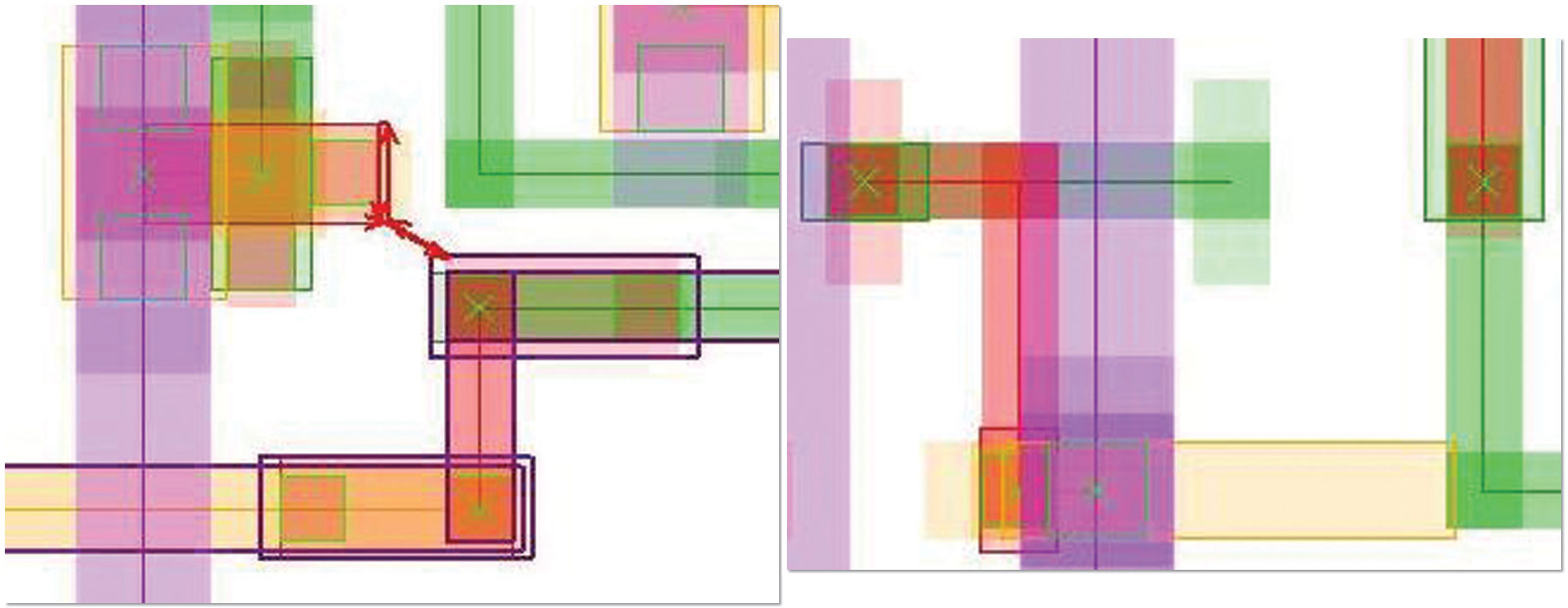
Figure 6
Some 1,400 instances of an end of line violation were detected and repaired without leaving the P&R environment
Sudhakar Jilla is the marketing director for Place & Route Products at Mentor Graphics. He holds a Bachelor’s degree in Electronics and Communications from the University of Mysore, a Master’s degree in Electrical Engineering from the University of Hawaii, and an MBA from the Leavey School of Business, Santa Clara University.
Mentor Graphics
Corporate Office
8005 SW Boeckman Rd
Wilsonville
OR 97070
USA
T: +1 800 547 3000
W: www.mentor.com