RTL debug: integrating automation and vizualization
Root-cause analysis of detected errors is a key design step. Debugging can take more than half of the verification effort. Vennsa’s OnPoint automated debug technology has been integrated with Springsoft’s Verdi visualization platform to reduce cost and uncertainty.
At a random point in the day, ask an engineer what he or she is doing. There is a good chance the answer will be, “Debugging.” It is said that functional debugging, and then dynamic or formal verification consume more than 60% of the time and cost of the verification cycle.
As the verification and design effort will increase four-fold by 2015, so will the debugging effort, notes Dr. Aart de Geus, chairman and CEO of Synopsys. That means new strategies that attack the debug problem are necessary.
The debug problem
Once functional verification fails, debugging is the process where the engineer identifies and fixes the root-cause of any failures.
There are many reasons why functional RTL consumes so many resources. First, there is increasing design size and the complexity of verification. Design processes comprise heterogeneous components implemented at multiple levels of abstractions (e.g., procedural, behavioral and synthesizable) using different languages (e.g., Verilog, System Verilog, VHDL and PSL) and ever-changing standards and protocols. Interacting with such elements adds layers of complexity and hinders transparency.
Then there are design specifications, often described in abstract models. They may not directly correspond to signals and transactions at the design level. The separation between these two layers can result in complications and misinterpretation during verification and debug.
A third often overlooked factor arises when a verification engineer works with unfamiliar code or third-party IP. Some develop expertise in specific blocks while others may familiarize themselves with broader but less detailed views of the design.
Additionally, when failures occur, bugs can cross module boundaries. When a design fails, the verification engineer may not be familiar with its intricate details, while the designer who has to make the fix probably has little familiarity with the verification environment in which it failed.
Verdi-OnPoint integration
Springsoft, a global supplier of specialized IC design software, and Vennsa Technologies, a specialist in automated failure analysis and error localization tools, recently integrated Springsoft’s Verdi Automated Debug System and Vennsa’s OnPoint Root Cause Analysis.
Enabled by the Verdi Interoperability App (VIA) platform, the integration gives engineers access to Verdi so that they can build fully customized tools to increase verification productivity and slash the chip debug burden with well-defined, automated functionality.
Verdi helps users navigate the design and verification environment to understand its intricacies, while OnPoint performs automated post-failure analysis of verification errors and localizes their sources without user involvement.
In this article, the integration serves as an example of how to mitigate difficulties outlined above.
The flow
The Verdi-OnPoint integration provides a single flow for automated root cause analysis and debug visualization. These tasks were previously disconnected and disparate.
Engineers run simulation tests as usual and generate value dump files into the Verdi fast signal database (FSDB) for failures they want to debug. OnPoint automatically reads in all appropriate files and settings needed for the Verdi system and FSDB file to perform reasoning and automated root cause analysis. The output of OnPoint is a set of suspects or lines in the source code that the engineer can change in order to fix the failure.
When engineers are ready to start debug, the Verdi GUI will contain OnPoint’s root cause analysis results. The Verdi source code viewer (nTrace), schematic viewer (nSchema) and waveform viewer (nWave) are synchronized with OnPoint’s suspects.
When considering one of OnPoint’s suspects, all of the Verdi views, features and related information are automatically presented to engineers in a familiar way.
As a starting point, the Verdi project setup is automated and generates the necessary file lists to pull in all required design files, libraries and options. An RC (configuration) file is generated that automatically sets the waveform viewer (nWave) to display all signals required for debugging. It pre-loads only the minimal circuit components into the schematic viewer (nSchema). As a result, as soon as the user calls the combined Verdi-OnPoint solution, everything is pre-loaded, all windows are preset to the relevant location and the user can focus on the fix.
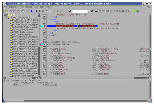
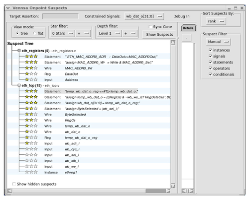
OnPoint’s supplies the user with a set of suspects and insights into the origin of a bug, how its effects are propagating and how the problem can be fixed. To improve user efficiency, suspects in the OnPoint suspect viewer are linked to the source code viewer (nTrace). When a suspect is considered, the corresponding location in the source is highlighted and centered in the source code viewer (Figures 1 & 2 below).
Figure 1
The Verdi/OnPoint source viewer in ‘highlight’ mode (Source: SpringSoft/Vennsa – click image to enlarge)
Figure 2
The Verdi/OnPoint source viewer in ‘suspect’ mode (Source: SpringSoft/Vennsa – click image to enlarge)
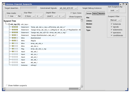
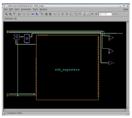
The Verdi-OnPoint integration includes a schematic viewer (nSchema) that only shows design instances, wires and functions associated with bug suspects to make it easy to navigate (Figures 3 and 4 below). This partial schematic view gives engineers a relevant view of how suspects are related and how they affect the failure point. Like the source code viewer, when a suspect is selected in the OnPoint suspect view, corresponding design instances in the schematic are highlighted. Further, the suspect list in the OnPoint suspect viewer is synchronized with the schematic view. This unified suspect/schematic view helps the design or verification engineer understand the source of failure and fix it with less effort.
Figure 3
The Verdi/OnPoint integration provides a synchronized suspect list (Source: SpringSoft/Vennsa – click image to enlarge)
Figure 4
The synchronized suspect list informs a partial schematic view (Source: SpringSoft/Vennsa – click image to enlarge)
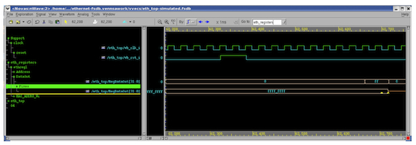
One of the most basic debugging aids is the waveform viewer. The Verdi and OnPoint integration enhances this concept-of-use model by showing how each suspect can fix waveforms of the verification problem. These waveforms (Figure 5) provide information about how signals associated with the suspect should behave so that they rectify the erroneous response for a given error trace. All fix waveforms are preloaded into the Verdi waveform viewer (nWave) and categorized so that engineers can easily browse easily the desired information. Each waveform is annotated to indicate the timestamp –– that is, the specific clock cycle of the simulated error trace –– where the fix value should take place to rectify failing outputs.
Further, with the Verdi annotation feature, fix values can be displayed in the source code view to allow engineers to identify the source of failure and fix errors with fewer debug iterations.
Figure 5
The Verdi waveform viewer displaying fix values (Source: SpringSoft/Vennsa – click image to enlarge)
Conclusion
Debug entails two tasks, searching for the source of an error and fixing it. The Verdi-OnPoint integration enables engineers to use one of the most widely deployed debug systems and enhance it with time-reducing automated root cause analysis. This integration gives the debug advantage to the engineer and provides the best of both worlds.
Contacts
Vennsa Technologies
555 Richmond Street West
Suite 702
P.O. Box 1201
Toronto, ON
M5V 3B1
Canada
T: 1-647-351-3708
W: www.vennsa.com
SpringSoft
USA Headquarters
1732 North 1st Street
#200
San Jose
CA 95112
USA
T: 1-888-668-2738
W: www.springsoft.com
