Reducing system noise with hardware techniques
Circuit noise problems can originate from a variety of sources. By carefully examining attributes of the offending noise you can identify it’s source, thereby making noise reduction solutions become more apparent. There are three subcategories of noise problems: device, conducted and radiated noise.
If an active or passive device is the major noise contributor, you can substitute lower noise devices into the circuit.
You can reduce conducted noise with by-pass capacitors, analog filters and/or rearrange positions of the devices on the board with respect to the power connectors and signal path.
You can minimize the contribution of radiated noise with a careful layout that avoids signal-coupling opportunities, inclusion of ground and power planes and system shielding techniques.
This article discusses and illustrates these strategies with reference to a data acquisition circuit using a load-cell sensor.
Transmission line reflection and ground bounce are two of the main issues that arise in any discussion of noise issues for digital circuitry. Generally, though, digital circuits operate with relatively large signal levels that have high noise margins, making them inherently immune to low-level noise pick-up.
If a circuit performs analog or data acquisition activities, a small amount of external noise can cause significant interference. For instance, 10mV of noise in the analog ground between a 12-bit analog-to-digital converter (ADC) and the converter’s driver amplifier can cause an error of eight least-significant-bits (LSB). In contrast, digital systems can tolerate hundreds of millivolts of this type of ground error before intermittent problems start to occur.
Finding the origin and then eliminating interfering noise in the analog domain presents a formidable challenge. Of particular interest are ‘slow’ sensor systems where designers are tempted to ignore problematic, high-frequency noise issues. This article looks at hardware noise reduction strategies for signal conditioning paths with sensors. It will explore noise topics such as conducted, device and radiated noise from an analog perspective.
Data acquisition circuit using a load-cell sensor
Figure 1 shows the example circuit used in this discussion. Its analog portion consists primarily of the load-cell sensor, a dual operational amplifier (op amp) (OPA2337 [4]) configured as an instrumentation amplifier, and a 12-bit, 100kHz SAR ADC (ADS7829 [4]).
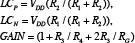
The sensor (LCL-816G [4]) is a 1.2kW, 2mV/V load cell with a full-scale range of ±32oz. In this 5V system, the electrical full-scale output range of the load cell is ±10mV. The instrumentation amplifier consisting of two op amps (A1 and A2) and five resistors creates a 153V/V gain. This gain matches the instrumentation amplifier block’s full-scale output swing to the ADC’s full-scale input range. The SAR ADC has an internal input sampling mechanism. With this function, each conversion produces a single digitized sample. The processor, for example the TMS320C6713B [4], acquires the data from the SAR converter, performs some calibration and translates the data into a usable format for tasks such as displays or actuator feedback signals.
The transfer function, from the sensor to the output of the ADC is:
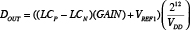
where:
In this equation, LCP and LCN are the positive and negative sensor outputs, GAIN is the gain of the instrumentation amplifier circuit. VREF is a 2.5V reference, which level shifts the instrumentation amplifier output, VDD is the power supply voltage and sensor excitation voltage, and DOUT is a decimal, whole number representation of the 12-bit digital output code of the ADC.
If the design implementation is poor, this circuit could be an excellent candidate for noise problems. The symptom of a poor implementation is an intolerable level of uncertainty over the digital output results from the ADC. It is easy to assume that this type of symptom indicates that the last device in the signal chain generates the noise problem. On the contrary, the root cause of poor conversion results could stem from the other active devices, from passive components, the PCB layout, or even extraneous sources.
For instance, if a designer did not take appropriate noise reduction measures, the 12-bit system in Figure 1 could output a large distribution of codes for a DC input signal as shown in Figure 2. The data it shows is far from an optimum implementation. Forty-four bits of peak-to-peak error changes the 12-bit converter system into a noise-free, 6.5-bit system.
Noise problems can be separated into these three subcategories:
- Device Noise. This originates in active or passive devices on the board.
- Conducted Noise. This appears in the PCB traces, and originates in devices on the board, or as a result of e-fields or b-fields.
- Radiated Noise. This is transmitted into the system via e-fields or b-fields.
Device noise
You can find device noise in both passive and active devices. The materials in passive devices can be films or composites. Resistors, capacitors, inductors and transformers fall into this category. The material in active devices is silicon. Active devices include bipolar transistors, field effect transistors, CMOS transistors and integrated circuits that use these transistors.
When you add device noise sources together, the equations are different from those used to describe voltage, current and number of bits. The fundamental difference is that noise signals are uncorrelated. Therefore, you implement a simple addition of voltage or current noise sources with an RSS formula, or the square root of the sum of the squares. If adding several voltage sources, you would use the following formula:

This formula applies to noise contributions over a specific bandwidth (BW). If there is no bandwidth definition, the particular test frequency must be used. In this case, the noise units are V/ÖHz. These units of measure describe the voltage noise density (also known as spot noise). Spot noise is measured at a specific frequency over a 1Hz bandwidth. Generally, the units of measure for voltage noise are: nV/ÖHz, mVrms or mVp-p.
Passive devices/Resistors
There are three basic classes of fixed resistors: wirewound, film type and composition. Regardless of construction, all resistors generate a noise voltage. This noise is primarily a result of thermal noise. Lower quality resistors such as the composition type have additional noise in the lower frequency spectrum due to shot and contact noise. Thermal noise (aka Johnson noise) is generated by the random thermal motion of electrons in the resistive material. This noise is independent of DC or AC current flow, and is constant across the entire frequency spectrum. The ideal thermal noise for resistors is:
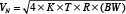
In this equation K is equal to Boltzman’s constant (1.38e-19), T is equal to temperature in Kelvin, R is the resistance value in Ohms, and (BW) is the noise bandwidth of interest.
Wirewound resistors are the quietest of the three and come closest to ideal noise levels. Composition resistors are the noisiest because of their contact noise, which is aggravated by current. Otherwise composition resistors have the same noise as wirewound. You can reduce resistive noise by reducing the value of the resistors on your board.
Active devices
This category of devices includes op amps, instrumentation amplifiers, voltage references and voltage regulators, among others. Two areas of voltage noise in the frequency domain are the 1/f and broadband regions.
The 1/f noise is a low-frequency noise where power density varies as the reciprocal of frequency (1/f). This noise is a consequence of trapped carriers in the semiconductor material, which are captured and released in a random manner. The time constant of this energy is concentrated within the lower frequencies. Figure 3 shows an example of 1/f noise.
Broadband noise is associated with the DC current flow across p-n junctions. This noise is due to a random diffusion of carriers through the base of the transistor and a random generation and recombination of whole electron pairs. You can reduce the noise that the active devices generate by selecting low-noise devices at the start.
Conducted noise
Conducted noise is the noise present on PCB traces. These problems can often be corrected at the point of origin.
Power supply filter strategies
Regardless of the power source, good circuit design implies that by-pass capacitors are used. While a regulator, DC/DC converter, linear or a switching power supply can provide power to the board, in all cases by-pass capacitors are a required part of the design.
By-pass capacitors belong in two locations on the PCB: one at the power supply (10mF to 100mF or both), and one for every active device (digital and analog). The value of each by-pass capacitor will depend on each device it is associated to. Generally speaking, if the device’s bandwidth is less than or equal to ~10MHz, a 0.1mF by-pass capacitor will reduce injected noise dramatically. If the bandwidth of the device is above ~50MHz, a 0.01mF by-pass capacitor is probably appropriate. Between these two frequencies, either or both can be used. In all cases, it is best to refer to the manufacturer’s guidelines for specifics.
By-pass capacitor leads must be placed as close as possible to the device’s power supply pin. If two by-pass capacitors are used for one device, the smaller of the two should be closest to the device pin. Finally, the lead length of the by-pass capacitor should be as short as possible in order to minimize lead inductance.
Signal path filtering strategies
A system such as that shown in Figure 1 requires an analog filter. The primary function of the low-pass, analog filter is to remove the input signal’s high-frequency components going into the ADC. If these high frequencies pass to the ADC, they will contaminate the conversion data by aliasing during the conversion process. To attenuate high-frequency noise, a two-pole, anti-aliasing filter is added to the circuit.
Layout strategies
Device placement is critical. In general, the circuit devices can be separated into two categories: high-speed (>40MHz) and low-speed. Then, they should be separated again into three sub-categories: pure digital, pure analog and mixed signal. The pure analog devices should be furthest away from the digital devices and the connector to ensure that digital switching noise is not coupled into the analog signal path through the traces or ground plane.
Emitted or radiated noise
A circuit’s level of susceptibility to extraneous noise is directly related to the implementing signal traces across the board, ground plane and power plane strategy, and subtleties such as using differential signal paths and shielding.
Signal traces
As a basic guideline, both analog and digital signal traces on PCBs should be as short as possible. Shorter traces minimize the circuit’s susceptibility to onboard and extraneous signals. The amount of extraneous noise that can influence the PCB is dependent on the environment. Opportunities for onboard signal coupling, however, can be avoided with careful design. One set of terminals to be particularly cautious with are the input terminals of an amplifier. Radiated noise problems can arise because these terminals typically have high-impedance inputs.
Signal coupling problems occur when a trace with a high-impedance termination is next to a trace with fast changing voltages. In such situations, charge is capacitively coupled between the traces per the formula:
I = CdV/dt (Formula 1)
In Formula 1, current is in amperes, C is capacitance, dV is change in voltage, and dt is change in time.
Ground and power supply strategy
Board layout definition, ground plane implementation and power supply strategy are critical when designing low-noise solutions. The PCB used in the data for Figure 2 did not have a ground plane. Ground planes solve problems such as offset errors, gain errors and noise problems.
The inclusion of the power plane in a 12-bit system is not as critical as the presence of the ground plane. Although a power plane can solve many problems, power noise can be reduced by making the power traces two or three times wider than minimum trace widths on the board.
Back to the drawing board
If we modify the circuit in Figure 1 with low-noise strategies in mind, we end up with the circuit in Figure 4. The PCB has an added ground plane, lower value resistors, lower noise amplifiers, a low-pass filter and by-pass capacitors. Figure 5 shows the resulting noise data in histogram form.
References
- Morrison, Ralph, Noise and Other Interfering Signals, John Wiley & Sons, 1992.
- Ott, Henry W., Noise Reduction Techniques in Electronic Systems, John Wiley & Sons, 1988.
- Allen, Holberg, CMOS Analog Circuit Design, Holt, Rinehart and Winston, 1987.
- These datasheets are available for download using the following URLs:
- “MicroSIZE, Single-supply CMOS Operational Amplifiers” (OPA337, OPA2337, OPA338, OPA2338), Texas Instruments, March 2005, www.ti.com/opa-ca.
- “100ppm/°C, 50mA in SOT23-3 CMOS Voltage Reference” (REF2912, REF2920, REF2925, REF2930, REF2933, REF2940), Texas Instruments, February 2008, www.ti.com/voltageref-ca.
- “10/8/12-bit High speed 2.7 V microPOWER Sampling Analog-to-Digital Converter” (ADS7826, ADS7827, ADS7829), Texas Instruments, June 2003, http://www.ti.com/ads7826-ca.
- “TMS320C6713B Floating-point digital signal processor”, Texas Instruments, November 2005, www.ti.com/tms320c6713b-ca.
- “Single-supply, Rail-to-rail Operational amplifier (OPA340, OPA2340, OPA4340),” Texas Instruments, November 2007, www.ti.com/opa340-ca.
- “0.5mV/°C max, single-supply CMOS Operational Amplifiers Zero Drift Series” (OPA334, OPA2334, OPA2335, OPA2335), Texas Instruments, www.ti.com/opa334-ca.
Texas Instruments
12500 TI Boulevard
Dallas
TX 75243
USA
T: 1 972 995 2011
W: www.ti.com