How PHY verification kits overcome traditional VIP limitations
Established physical layer verification IP packages focus so much on protocols they miss problems that arise from the broader context. A PHY verification kit bridges the gap.
Because of complexities in the design flow, traditional verification IP (VIP) packages tend to overlook subtle aspects of physical layer (PHY) verification focusing more on the protocol than its wider context. This often leads to costly debug late in a project’s lifecycle.
In addition, because of the variety of possible topologies in a PHY implementation, it is hard to completely exercise the role and related functionality of a PHY using traditional strategies.
Given the analog signaling and homologous functionality of the PHY in serial protocols, the industry has defined common PHYs for use with multiple standards. These segregate the PHY logic from that of the general ASIC. One such common PHY is used with PCI Express, with both USB 3.0 and 3.1, and with SATA. Similarly, M-PHY is used with SSIC, with M-PCIe, and with LLI protocols, among others.
The PHY common to PCI Express, USB 3.0/3.1, and SATA devices helps accelerate development by implementing the physical layer functionality as a discreet IC or macro cell that can be easily incorporated in an ASIC design.
In bus-based layered protocols, the PHY typically provides the following functionality:
- Various serial data transmission rates
- An 8, 16, or 32-bit parallel interface to transmit and receive data
- Recovery of data and clock from the serial stream
- Holding registers to stage transmit and receive data
- Direct disparity control to transmit compliance patterns
- Various encode/decode and error indications
- Receiver detection
- Beacon transmission and reception
- Low Frequency Periodic Signaling (LFPS) transmission
- Selectable Tx margining, Tx de-emphasis, and signal swing values
- COMINIT and COMRESET transmission and reception
- Multi-lane de-skew
A comprehensive PHY verification plan must verify all related functionality in various conditions. However, a traditional VIP tends not to do this.
Note: In this article, PHY features are described in the context of PCI Express and USB. However, in terms of the PHY verification methodology, our observations apply to all serial protocols that use a common PHY.
PHY verification environment
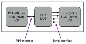
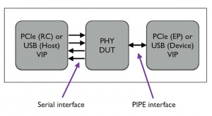
Usually, a PHY verification environment requires one bus functional model (BFM) at the serial interface and another at the PIPE interface.
In Figure 1, the VIP acts as the USB host or the PCIe RC at the PIPE interface, and as the USB device or the PCIe EP at the serial interface.
However, in Figure 2, the connections are flipped.
(Note: The VIP here refers to a model that has the BFM, stimulus generator, coverage collector, and a protocol checker.)
For comprehensive verification of the PHY, the testbench must enable the same stimulus to run in both cases illustrated above without requiring any changes to the testbench.
The limitations of a traditional VIP for PHY verification can be resolved with a comprehensive, specifically-tailored PHY verification kit made up of the following phases:
A. Initial Phase
- Pin Connections
- Configuration
- Link Up and First Transaction
B. Verification Phase
- Test Plan
- Test Case
- Test Run
- Debug
C. Regression Phase
- Regression Environment
- Coverage Metrics
Let’s now look at each of those phases individually.
Initial phase
A traditional VIP focuses on protocol verification and provides connections for the specific configurations associated with the serial and PIPE mode. Moreover, because of the variety of configurations possible when setting up the pin connections, a traditional VIP also tends to ignore the intricacies of achieving an accurate PHY connection. This is a major limitation of traditional strategies when it comes to the following integral areas of a design:
- Protocol specification version
- PIPE specification version
- ECNs supported by PHY
- Signals supported by PHY
- Width of each signal
- Clock frequency required by PHY
- Reset mechanism
A PHY verification kit overcomes these limitations by focusing on PHY connections for all possible configurations. This minimizes the risk of issues that arise out of inaccurate connections.
Pin connection error scenarios
Here are five typical error-prone scenarios that might be encountered when setting up the pin connections.
- The data pin for a 16-bit PIPE with four lanes can be declared as a single pin of 64 bits or four separate wires of 16 bits each. In a case where the data pin is declared as a single pin of 64 bits, it is hard to determine whether the [15:8] index represents the first byte of the second lane or the second byte of the first lane. So in this case, a wrong connection might lead the connection to link up on fewer lanes than required. Debugging this issue at a later stage in the verification cycle often requires significant time and effort.
- The signal width varies across different versions of the PIPE specification. For example, TxDeemph is an 18-bit signal in the latest specification, but was a 1-bit signal in an earlier specification. So a common mistake in this case is to leave the signal unconnected or to a supply bit-wise OR of 18-bit TxDeemph to the PHY.
- On the PIPE interface, some signals are shared, while some are per-lane. For example, the PowerDown signal width is 3 bits in the latest specification but was 2 bits in an earlier one. Here, issues in the connection link-up may arise if this signal is per-lane in the DUT and is declared as a segregated signal for all lanes. A similar issue could occur where the Rate signal is 2 bits in the latest specification but was previously 1 bit.
- The PHY can generate the clock or, alternatively, the testbench can supply the clock externally. Here, a problem occurs when either of the devices misses the clock connection or there are multiple drivers on the clock. Typically, the GEN1 clock is supplied externally. Here when the connection speed changes, the clock remains GEN1 and this causes problems.
- Leaving reset unconnected, keeping reset always on, or keeping the reset duration too short or too large. These are some common issues in the case of the reset connection.
(Note: A connection file in the PHY verification kit contains special notes for the signals where the width changes across different versions of a specification. These notes provide guidelines to connect a signal that requires particular attention.)
Many other error-prone scenarios can arise depending on the design being verified. While the use of a PHY verification kit minimizes the risk of encountering such problems, it cannot eradicate them. Nevertheless, it does allow engineers to focus on the main configuration problem in PHY verification: To enable VIP features that are not supported in the PHY.
Configuration error scenarios
Here are five examples of error-prone scenarios that might be encountered during configuration:
- The VIP is configured for a clock frequency transition when the PHY supports changing the PIPE width during speed change. This configuration causes deadlock.
- In the PIPE width change configuration, the engineer forgets to set the initial PIPE width at which the link-up must occur.
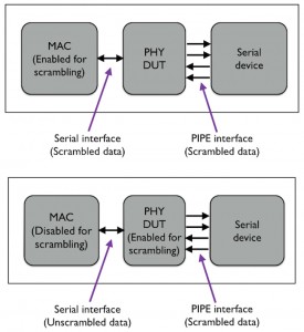
- Generally, MAC performs data scrambling on the PIPE interface. However, if the PHY is also configured for scrambling, this configuration leads to unrecognized data at the other end. See Figure 3 below.
- While configuring the loopback master, the engineer configures both VIPs at the serial and PIPE interface as the loopback masters. Generally, only the VIP at the PHY side is configured as the loopback slave. The VIP at the other side must be configured as the loopback master. A wrong configuration in this case causes problems in the loopback state.
- Generally, the LTSSM timers are configured according to the protocol specifications. A faster simulation can be achieved by adjusting the timer values according to the PHY requirements.
Configuring or debugging issues because of an incorrect or unset PHY configuration takes a lot of time if the problem is caught only late in the verification cycle. You always want to set the correct configuration at the beginning. A PHY verification kit enables engineers to set all the relevant PHY configurations at that very time.
Link-up error scenarios
After the engineer finishes connecting the pins and setting up all relevant configurations, the next objective is to ensure the connection link-up and initiate the first transaction. More often than not, link-up issues occur during the initial PIPE signal handshaking (e.g., receiver detection).
Here are eight examples of the error-prone scenarios that might be encountered during this link up process:
- No receiver detection initiative from MAC occurs because PHY configured the Phystatus signal as low.
- The PHY requires another receiver detection attempt.
- The PHY does not respond to the receiver detection attempt because of a reset issue.
- The PHY does not respond to the change in the PowerDown signal.
- Timing of the RxElecIdle signal is not correct, which causes even the valid packet to be truncated in the middle.
- During the first equalization process, the PHY does not respond because of incorrect coefficient values.
- During the first speed change, the PHY does not respond to the change in the Rate signal from the MAC.
- The PHY is unable to perform a speed change in the recovery speed because of a short timer value.
Given these risks and their context, a PHY verification kit includes a comprehensive troubleshooting note that helps users debug several issues in the PHY link-up process and also provides timing details for each signal.
Verification phase
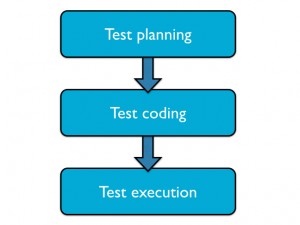
In the verification phase, engineers follow a test plan, write the test cases, and then run those cases. This is when things get hardcore.
The test cases must be robust. In our particular context, the process for writing PHY test cases is slightly different from that for writing cases for the physical layer of a SoC.
For example, consider a VIP that provides a test suite for all layers. Can the physical layer test suite alone be extracted to verify the PHY? Yes… probably. However, can the extracted test suite provide comprehensive PHY verification? Probably not: The physical-layer test suite targets the protocol SoC and, in some specific cases, particular tests might not cover standalone PHY verification requirements.
Also, specific test cases might be required to cover standalone PHY verification corner cases, such as a test case to verify whether a PHY performs the frequency compensation.
A PHY verification kit removes these limitations by providing a test suite with a test plan that targets 100% PHY verification.
Here are more examples of test cases targeting stand-alone PHY verification:
- To inject a disparity error from the serial side and expect decode or disparity error code in the RxStatus signal on the PIPE side.
- To configure the serial side as the loopback master and check if the PHY performs loopback after seeing the asserted TxDetectRxLoopback signal from the MAC side.
- To create some frequency difference between the serial and PIPE clock and check whether the PHY performs the SKP addition deletion.
- To check for the receiver underflow or overflow situation by creating frequency differences and stopping the SKP signal from the serial side.
- To configure the serial side to perform polarity inversions on the differential pin so that the MAC asserts the RxPolarity signal. Then check whether the PHY performs the polarity inversion on the data received from the serial side.
- To exercise all the power saving states and check the behavior on the electrical idle state exit and entry.
Regression phase
A robust regression environment meets the following six criteria:
- The design can be compiled independently.
- The testbench can be compiled independently.
- The individual tests can be run in parallel.
- Any test failures can be easily checked and reproduced.
- Log files and waveform file names show an association with the tests.
- Individual test coverage data is saved to the Universal Coverage Database (UCDB) format for coverage metrics.
A PHY verification kit offers such an environment, one that ensures that any change in the design or the testbench can be easily validated by running all the tests in one go. This saves time and eliminates manual effort.
Engineers can keep track of verification objectives with the help of functional and code coverage metrics. They can track code coverage using switches in the simulator. To track the functional coverage, they can use covergroups, coverpoints, or crosses in the verification plan.
In the verification plan – generated as an XML file – all the available covergroups, coverpoints, and crosses are mapped to individual sections of the protocol specifications.
Once the required covergroups are enabled, the coverage data needs to be saved in the UCDB format so that the team can view the coverage metrics in, for example, the Questa simulator from Mentor Graphics. The UCDB is a repository for all the coverage data (including code coverage, cover directives, cover points, and assertion coverage) that is collected during simulation. The Questa verification platform also enables all the coverage results to be merged in the UCDB format, and they are then accessible in the Questa GUI or as a log file.
Engineers can also enhance or modify the XML plan according to their requirements. The PHY verification can then be signed-off once the desired coverage goal is achieved.
Conclusion
The limitations of traditional VIP packages for PHY verification can be resolved using an exclusive PHY verification kit. Such kits offer the following advantages:
- Faster link-up with a concurrent focus on accurate connections and correct configurations with a large number of signals, varying widths across specification versions, and complex timer configurations.
- A specific test plan, which targets all PHY scenarios, to deliver definitive closure on PHY verification.
- A standard regression environment to run all test cases in parallel and exclusively analyze test results.
To learn more about how to use UVM-based verification IP for protocols such as PCI Express, MIPI CSI, and DSI, check out our webinar New School Thinking for Fast and Efficient Verification Using EZ-VIP.
References
PHY Interface for the PCI Express, SATA and USB 3.1 Architectures, Version 4.2 specification
Universal Serial Bus 3.1 specification
USB 2.0 PHY verification paper: http://www.design-reuse.com/articles/15011/usb-2-0-phy-verification.html
Amit Tanwar and Manoj Manu are members of the consulting and technical staff specializing in verification IP at Mentor Graphics, Noida, India.


