How to use PCI Express in low-power mobile SoCs by exploiting M-PCIe
How to use PCIe in low-power SoCs by swapping the standard PCIe PHY for M-PCIe, defined by MIPI for mobile use
Since PCI Express was launched in 2002 as a replacement for PCI, PCI-X and AGP, it has become the interconnect standard of choice within enterprise and high-performance computing applications.
This popularity has lead to incursions into other markets, such as the digital home/office, and laterally, wireless and mobile multimedia. Each market makes different demands of the standard: pure performance for the enterprise equipment; cost and integration for the digital home/office space; and power efficiency for mobile applications.
Reducing PCIe power
Efforts to reduce the power used by the PCI, and lately PCIe, interfaces can be traced back to 1997 with the introduction of the PM 1.0 (power management) specification, addressing the power consumption of idle devices.
The introduction of PCIe 1.0 in 2002 brought with it a definition of Link power states (Ln) and active state power management (ASPM).
In 2009, dynamic power allocation (DPA) followed, defining ways to manage the power envelopes for active devices. This was followed in 2012 with L1 sub-states (L1 SS), which defined ways to shut off sub-blocks of the PHY to save energy.
Despite these efforts, the mobile market, which is currently using PCIe 2.0 at data rates of up to 5Gtransfer/s, wants further power reductions. There are two main issues to overcome to achieve this: the power consumed by the PHY specified by the PCIe standard is too high; and its latency when moving in and out of low-power states is too high for use in highly responsive mobile devices.
Choosing another PHY
A collaboration between the PCI-SIG and the MIPI Alliance has brought a solution: using the mobile PHY (M-PHY) already defined by MIPI to provide the physical interface for PCIe when used in mobile settings. The result is known as M-PCIe.
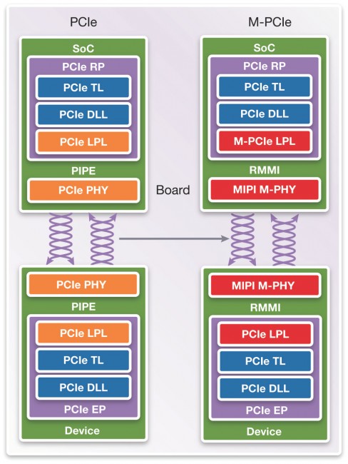
M-PCIe preserves the higher (transaction and data link) layers of the PCI specification and the PCIe programming model, but replaces the PCIe PHY with the M-PHY. This means changing a number of parts of the overall PCIe channel. Within the PCIe SoC, the PCIe lower physical layer (LPL) has to be replaced with the equivalent M-PCIe LPL. The link from the lower physical layer to the PHY, normally implemented using the PIPE specification, has to be exchanged for the RMMI approach specified by MIPI.
Fig 1 Using M-PHY means changing the lower physical layer and PHY interface (Synopsys)
Using the M-PHY in mobile applications enables more aggressive power management strategies, such as short-channel circuit optimizations, and lower power consumption in Stall, and Hibernate states.
Comparing PCIe PHY and the M-PHY, the M-PHY offers a number of advantages to mobile designers:
- The power targets for M-PCIe are a Link idle power consumption in the microwatt range, and a reduction of the active power consumption of between 2 and 5x.
- The power consumption attributable to the PCIe PHY and the M-PHY. At 2.5Gtransfer/s the M-PHY uses 50 to 60% less power than the PCIe PHY. At 5Gtransfer/s the advantage is 30 to 40%.
- Latency also improves: while it may take a PCIe PHY a few microseconds to exit from a low power state, the M-PHY will do the same in hundreds of nanoseconds.
- The M-PHY is inherently lower power, since it is designed to drive shorter trace lengths as used, for example, on a mobile-phone PCB, than in enterprise equipment such as servers.
- The M-PHY is designed to move between different use states, e.g. from data transfer to stall to hibernate, quickly, to save as much power as possible.
- The M-PHY specification allows asymmetric link widths, rather than the Tx/Rx pairs specified with PCIe PHY. This means that you don’t have to create and drive SERDES and PCB traces that will be unused, reducing design complexity and saving power.
- There are other differences: the M-PHY symbol clock frequencies aren’t neat multiples, but have been chosen instead not to interfere with key frequencies used in mobile handsets and networks.
Design issues
Swapping from the PCIe PHY to the M-PHY isn’t without challenges. For example, using the M-PHY means using a new link-training and status state machine (LTSSM), to control the M-PHY’s low-power status. Implementing the LTSSM will require a lot of validation.
The change in the link to the PHY, from using the PIPE specified for PCIe PHYs to using RMMI (the reference M-PHY module interface), also presents design challenges. RMMI introduces an elastic buffer on the MAC side (controller), which makes comparing latencies between the two approaches more difficult. Because it was not originally developed for PCI Express use, the RMMI interface also lacks specifications for other attributes, such as the Tx symbol clock rate, which may make interoperability between controllers and PHYs more difficult.
M-PCIe implementation
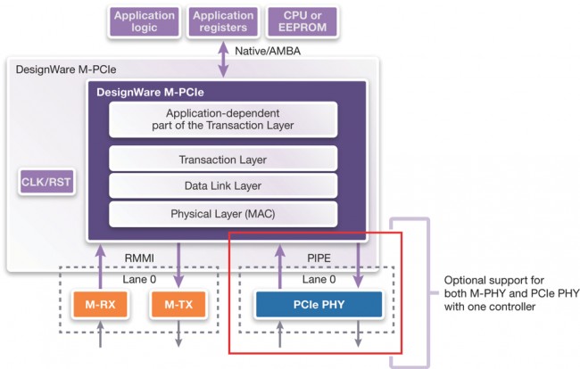
Synopsys offers a DesignWare implementation of M-PCIe, built on its DesignWare PCIe offering, in a number of variants. The controller architecture has been adapted slightly so that users can opt to support either (or both) PCIe PHY and M-PHY approaches from the same controller.
Figure 2 It’s possible to support both the PCIe PHY and M-PHY with one DesignWare controller (Source: Synopsys)
The block maintains the silicon-proven features of the PCIe PHY version, and the application interfaces. The power management is compliant with the PCIe PCI-PM and ASPM specifications.
On the software side, the block is compatible with existing PCIe programming models, and uses the same registers for configuration/port logic. Additional registers are provided to control the attributes of the M-PHY. This approach should make it easier to migrate designs from PCIe to M-PCIe with minimal changes.
Further information
White Paper: USB 3.1: Evolution and Revolution
White Paper: Reducing Power Consumption in Mobile Applications with High-Speed Gear3 MIPI M-PHY IP
Synopsys DesignWare IP Solutions for PCI Express
Author
Richard Solomon, technical marketing manager PCIe controller IP, Synopsys


