A map of the prototyping ecosystem
Different users within a design team will have varying needs for prototype capabilities. What type of prototype to pick is not always 100 per cent clear. Here are some pointers on how to make the choice.
The electronics industry has accepted the fact that system development without prototyping is risky. There are, however, several different types of prototypes—both software and hardware based—that allow hardware/software integration, verification, and debugging. In addition, different users within a design team have potentially different needs for prototype capabilities. What type of prototype to choose is not always 100 per cent clear.
The multitude of choices can make it hard for design teams to find the right combination of prototypes to support their needs. Analysts IBS and Semico estimate that by 2015, design teams will need to integrate on average more than 130 IP blocks, with reuse exceeding 70 per cent of their design. More than 60 per cent of the chip-related development effort will have moved into software, a factor complicated by the rise of multicore designs that require software be distributed across cores.
Design teams will face significant low-power issues, and designs will become more and more application specific, with high analog/mixed-signal content and very complex on-chip interconnect structures. Figure 1 shows an example chip-design flow with some of the key milestones and dependencies. The lower half indicates some of the major project steps as averaged from an analysis of 12 projects.
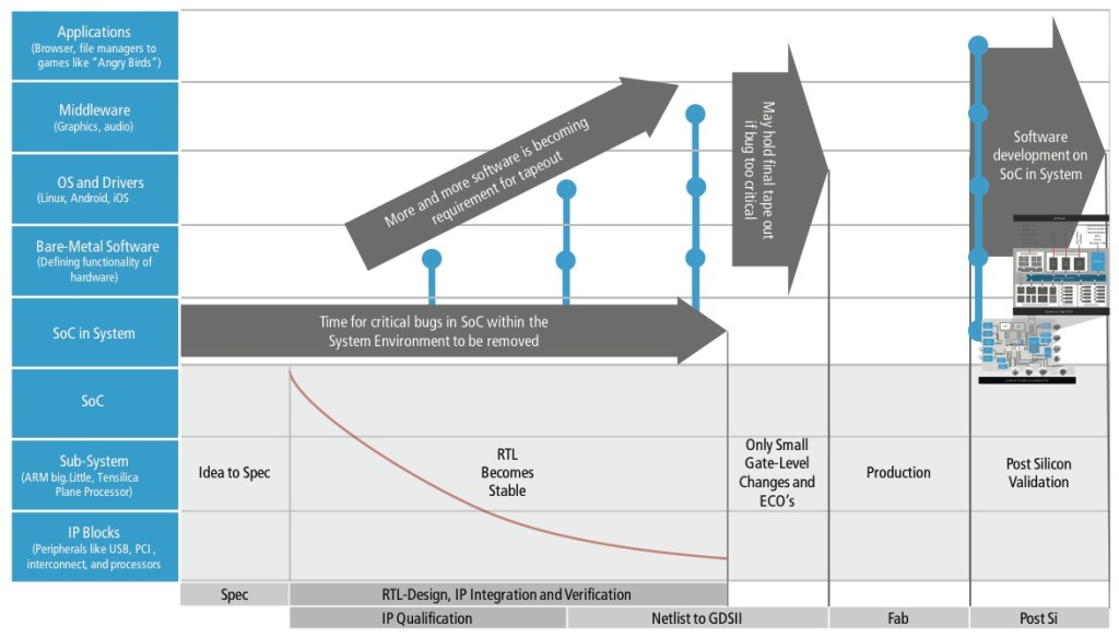
Figure 1 An example design flow with key milestones and dependencies (Source: Cadence)
A specification phase of 8 to 12 weeks is followed by a phase combining register transfer level (RTL) design, integration, and verification, with a major factor these days being the qualification of IP. The overall duration from RTL to GDSII at tapeout ranges from 49 to 83 weeks. A key point is that only small gate-level changes and engineering change orders (ECOs) are allowed in the last 10 to 12 weeks, as the focus of development shifts to silicon realization. The actual tapeout is followed by an 11 to 17 week production phase and 14 to 18 weeks of post-silicon validation.
The left axis indicates the hardware/software development stack. The SoC is integrating sub-systems and IP blocks and then operates within its system environment. Different types of software execute on the SoC, from bare-metal software that, together with its associated hardware, defines the functionality of subsystems on the IC, to drivers and operating systems. The operating sytems in turn host middleware for audio, video, graphics, and networking. Those services in combination enable the end applications that define the end-user experiences.
Hardware/software interactions
Interactions at the hardware/software interfaces should be validated as early as possible. Today, a successful boot of operating systems has become a de-facto requirement to allow tapeout. This requirement poses challenges for RTL execution engines as a large number of cycles must be executed simply to get operating systems to boot.
To provide greater performance to software developers and allow the focus between hardware and software to change, it makes sense to divide the verification process between four different core execution engines: virtual prototypes; RTL simulation; acceleration and emulation; and FPGA-based prototypes.
Virtual prototypes are either architectural or software-based. Architectural virtual prototypes are mixed-accuracy models that enable architecture decision-making. Parameters such as bus latency and contention, and memory delays are described in detail, maybe even as small portions of RTL. The rest of the system is abstracted as it may not exist yet. The main target users are system architects.
Architecture virtual platforms are typically not functionally complete and they abstract environment functionality into traffic driving the architectural model. Specifically, the interconnect fabric of the previous examples is modeled in full detail, but the analysis is done per subsystem. Execution speed may vary greatly depending on the amount of timing accuracy, but normally is limited to tens to the low-hundreds of kilohertz.
Software validation
Software-based virtual prototypes run the actual software binary without re-compilation at speeds close to real time – potentially hundreds of megahertz. Target users are software developers, both apps developers and hardware-aware software developers. Depending on the need of the developer, some timing of the hardware may be more accurately represented.
This prototype can be also used by hardware/software validation engineers who need to see both hardware and software details. Due to the nature of just-in-time binary translation the code stream of a given processor can be executed very quickly natively on the host. The fast execution makes virtual prototypes good for software development, but modeling other components of the example systems, such as 3D graphics accelerators, would result in significant speed degradation.
RTL simulation executes the same hardware representation that is later fed into logic synthesis and implementation. It may only execute in the single-hertz range, but it is hardware accurate as the RTL will become the golden model for implementation, allowing detailed debug.
Acceleration and emulation
Verification acceleration executes a mix of RTL simulation and hardware-assisted verification, with the testbench residing on the host and the design under test (DUT) executing in hardware. As indicated by the name, the primary use case is acceleration of simulation. This combination allows engineers to utilize the advanced verification capabilities of language-based testbenches with a faster DUT that is mapped into the hardware accelerator. Typical speed-ups over RTL simulation can exceed 1000x but the maximum is typically limited to tens of kilohertz.
Emulation executes the design using specialized hardware – verification computing platforms –into which the RTL is mapped automatically and for which the hardware debug is as capable as in RTL simulation. Interfaces to the outside world, such as Ethernet and USB, can be made using rate adapters. In-circuit emulation (ICE) takes the full design and maps it into the verification computing platform, allowing much higher speed-up into the megahertz range, which enables hardware/software co-development.
Although the ICE typically executes the design within its system environment, testbenches can be supported using so-called synthesizable or embedded testbenches (STBs, ETBs). These are mapped into the verification computing platform to allow faster execution than verification acceleration itself.
FPGA-based prototyping uses an array of FPGAs into which the design is mapped directly. Due to the need to partition the design, re-map it to a different implementation technology, and re-verify that the result is still exactly what the incoming RTL represented, the re-targeting and bring-up of an FPGA-based prototype can be cumbersome and take months (as opposed to hours or minutes in emulation) and hardware debug is a difficult process. In exchange, speeds will go into the tens of megahertz range, making software development a realistic use case.
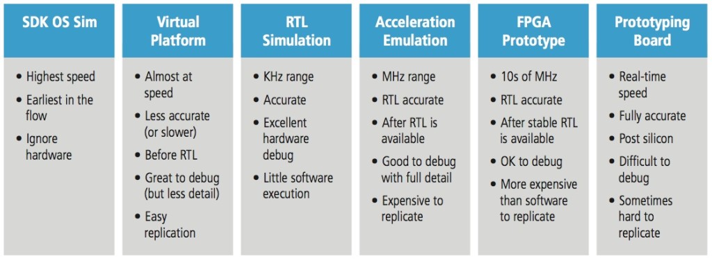
Figure 2 Key characteristics of hardware/software development engines (Source: Cadence)
Figure 2 illustrates the key upsides and downsides of the four core engines together with two additional flanking engines, software development kits (SDKs) in the front, and the actual silicon-based prototype after the four core engines.
SDKs typically do not run the actual software binary but require re-compilation of the software. The main target users are application software developers who do not need to look into hardware details. SDKs offer the best speed but lack accuracy. The software executing on the processors, as in the SoC examples given earlier, runs natively on the host first or executes on abstraction layers like Java. Complex computation, as used in graphics and video engines, is abstracted using high-level APIs that map those functions to the capabilities of the development workstation.
Prototyping with silicon
Silicon-based prototypes come in two incarnations. First, like the SDK in the pre-RTL case, the chip from the last project can still be used, especially for apps development. However, the latest features of the development for the new chip are not available until the appropriate drivers, OS ports, and middleware become available. Second, there is the actual silicon prototype once the chip is back from fabrication. Now users can run at real speeds, with all connections, but debug becomes harder as execution control is not trivial. At that level, the execution is also hard to control. Starting, stopping, and pausing execution at specific breakpoints is not as easy as in software-based execution, FPGA-based prototyping, and acceleration and emulation.
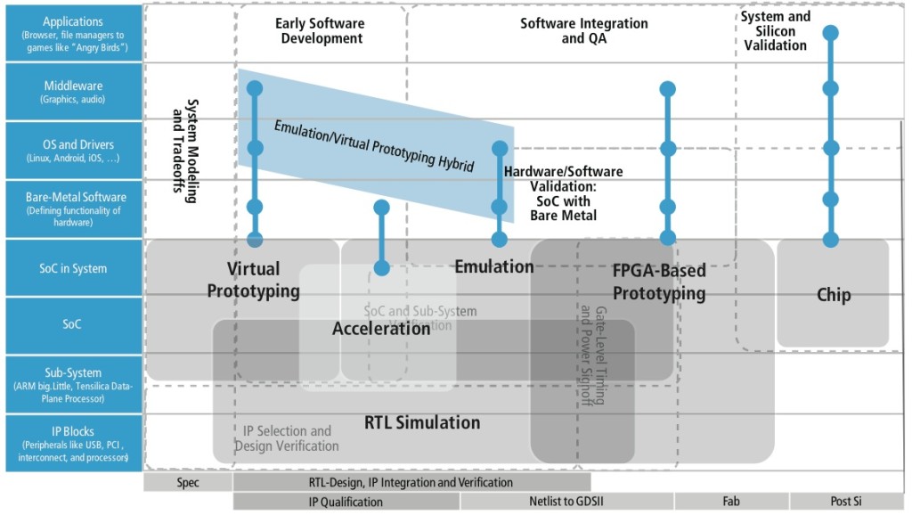
Figure 3 Execution-engine sweet spots for verification and software development (Source: Cadence)
Each of the modelling and simulation techniques has a different sweet spot in the hardware/software verification process, and can be summarized as shown in Figure 3. For example, application software developers need a representation of the hardware as early as possible. It must execute as fast as possible and must be functionally accurate. This type of software developer would like to be as independent from the hardware as possible, and specifically does not need full timing detail. For example, detailed memory latency and bus delays are usually not of concern.
For hardware verification engineers, accuracy definitely trumps speed, although the faster the prototype executes, the better the verification efficiency. This type of user also cares about being able to reuse testbenches once they have been developed.
What is important in the verification flow is that migration between the different forms of simulation and acceleration are made as seamless as possible. As the different execution engines grow closer together, efficient transfer of designs from engine to engine with efficient verification reuse as well as hybrid execution of engines will gain further importance. This why Cadence has organized its verification support around the four main pillar engines of virtual prototyping, RTL simulation, acceleration/emulation and FPGA-based prototyping and ensured that these different techniques can be deployed as needed.
This article forms the first part of a pair of articles on emulation – the second will focus on performance and predictability.
Author
Frank Schirrmeister is Senior Director at Cadence Design Systems in San Jose, responsible for product management of the Cadence System Development Suite.
Company info
2655 Seely Avenue
San Jose, CA 95134
(408) 943 1234
www.cadence.com