Making SiP happen in 3D
System-in-package (SiP) used to be thought of as a ‘poor man’s system-on-chip’ (SoC). Not any more. The complexity involved in implementing various levels of functionality on a single SoC is reaching such levels that it is becoming increasingly difficult to justify the design and manufacturing costs. Similarly, the need to deliver products within equally tight (and sometimes tighter) time budgets means that the reuse of intellectual property and proven blocks, where possible, is highly desirable. Certainly, no one wants to re-invent the wheel.
SiP itself is beginning to offer a number of techniques that provide SoC-like levels of integration and meet demands from performance through to form factor. Such techniques include stacked die and through-silicon vias. Although talked about for some time, they are only now beginning to become more widely available from semiconductor foundries.
This special article takes the form of an interview with Tom Quan, deputy director of design services marketing at TSMC, the world’s largest foundry. The company included SiP in its Reference Flow 10, launched at this year’s Design Automation Conference. Quan discusses TSMC’s views on SiP’s market position, tools for its realization and the technical challenges, among other issues.
At the 2009 Design Automation Conference, TSMC, the largest semiconductor foundry, unveiled its latest approved design flow. For the first time since these were formally launched in 2001, Reference Flow 10 included elements specifically aimed at system-in-package (SiP), such as SiP package design, electrical analysis of package extraction, timing, signal integrity, IR drop, and thermal to physical verification of design rule checks and layout-vs.-schematic.
Multi-chip modules are nothing new. The big difference with this take on SiP, however, is that it implies the use of technologies that promote the overarching technique more clearly as an alternative to highly integrated, single silicon systems-on-chip (SoCs). Foremost among these are 3D stacking and through-silicon vias (TSVs).
Again, these technologies have been discussed and even seen in the lab in many different forms over the last five years, arguably for longer than that. For 3D stacking, the technique is already in use in the memory sector. However, until now there has been some reticence, particularly on the part of foundries, to promote their use in high-volume design. There are some good reasons for this.
TSVs are discussed in more detail below, but suffice it to say here that, as the name suggests, they involve drilling through a wafer, an idea that is enough to make even the least manufacturing-aware designer wince on first confronting it.
Source: TSMC
|
SoC |
SiP |
|
Single tech node |
Multiple tech node |
|
All IPs ported to same technology node |
Mix of IPs in diff technology nodes |
|
Horizontal partitioning |
Horizontal & vertical partitioning |
FIGURE 1 SiP opportunities
Similarly, the interplay between various pieces of such a system may work to compound and worsen the traditional metric that the yield of any package is the multiple of the yield percentages for each IC within it.
Tom Quan, deputy director of design services marketing at TSMC, acknowledges that there is such an emphasis on the manufacturing side of SiPs that his company’s position needs to be sufficiently confident it can deliver chips that yield in commercially viable quantities, “based not just on what we can provide, but on what comes from the entire ecosystem.”
Such is the nature of SiP that even though an error may be introduced outside the manufacturing process—indeed, the scope for this happening is substantial—the foundry could nevertheless see its credibility damaged by errors elsewhere in the chain.
At the same time, there is a SoC bottleneck that is leading some of TSMC’s larger customers to push for the availability of SiP alternatives, and Quan acknowledges that his company also sees this problem.
The SoC bottleneck
“If you are building an SoC today, there are perhaps four main types of issues that the customer faces,” says Quan. “First, there is cycle time. The bigger the design, the longer it takes—now, if you are looking at a 100M gate SoC design, you are likely to need more than a year to complete it with more than 50 engineers on your team.”
Source: TSMC

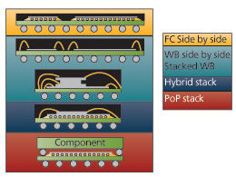
FIGURE 2 Traditional SiP configurations
“Second, the IP [intellectual property] you need is not always available for the latest technology that you want to put the SoC on.
“Third, not all IP shrinks in the same way—it is not uniform. For example I/Os haven’t changed that much at all. They’re pretty much the same size in 0.13um, 90, 65 or 45nm. Analog has changed but still more slowly than the shrinks, much more slowly. And so on.”
“Fourth, all the design challenges are increasing in areas such as power density, signal integrity, design-for-manufacture [DFM] and so on.”
These are familiar issues and also stretch into concepts such as the crosstalk present when things are crammed in closer than ever before, the increasing number of layout-dependent defects and increasing power in a given area as gate density increases.
“And we see this because SoC targets one node,” says Quan. “SiP can combine things from different nodes. If your IP works well at one node then it doesn’t need to be migrated, for example. Also, you can look at integration in a different way, putting things on the vertical as well as the horizontal axis” (Figure 1).
There are a number of traditional SiP techniques—flip-chip, side-by-side, stacking, wirebonding (Figure 2)—that have been in use for some time, but which also have significant limitations particularly in terms of performance (especially over the communication links between the different pieces of silicon) and size (particularly for smaller portable devices aimed at the consumer electronics space).
Source: TSMC
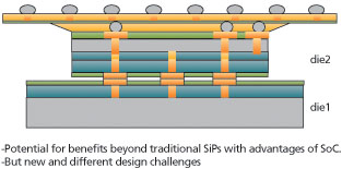
FIGURE 3 3D stacking with TSVs

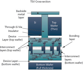
TSVs are electrical connections, typically copper filled, created by drilling straight through a number of wafers and then stacking these. Not only does this technique reduce the footprint, but it also greatly shortens electrical paths (certainly in comparison with wirebonding to edge-of-chip I/Os) between different parts of the SiP to boost performance (Figure 3 and Figure 4).
Stacking the die in a 3D configuration essentially gets the different parts to act together as a single IC, and this can be achieved in a number of ways, the two foremost being front-to-back and front-to-front.
Then there are opportunities for a major boost in the I/O. “It doesn’t have to be on the boundary anymore—you can connect directly in the middle of the die. If you look at SoC flooplanning today it is I/O limited. Once you get up to 1,000 I/Os, the chip can result in being very big even if the core is very small, and that is about the upper limit. But with SiP, you can get to 1,000 and beyond.”
The RC of the interconnects is also thought to be lower, so that rather than having big I/O device drivers, you can use smaller standard drivers, again helping in terms of size and efficiency.
“There are some big opportunities here,” says Quan. “But there are some significant challenges.”
SiP today
SiP technology has been seen in some quarters as a “SoC made easy,” although a senior executive with a Tier One semiconductor vendor says that he prefers now to see the comparison in terms of “a world of relative pain.” Earlier notions of simply putting different functional and IP elements side by side have been overtaken by the use of new technologies in the drive for performance, cost and market advantages. Quan broadly agrees that the task is not as simple as it might first appear, and highlights a number of illustrative challenges.
TSV SiP cross section

FIGURE 4 TSV SiP cross section
“The design flow is affected,” he says. “You need to have some sort of methodology that integrates chip design and package design together. Today, these two teams usually work independently and pass the basic model back and forth, with the die designer assuming some ideal package and the package designer assuming an ideal die. What you don’t have that often is a package-aware design and you really need that for SiP.”
A crude example of the potential problem here would be to go through the entire process of achieving the stack design only to discover that it requires a ceramic package that would put the finished component cost beyond viability. Consequently, silicon/package co-design is highlighted as a specific area that customers need to address within Reference Flow 10.
Then there are also some specific issues. Here are five of the most sensitive that TSMC has also incorporated in the new flow.
Static timing analysis needs inter-die timing strategies that also calculate the effect of the package to reduce margins.
Die that share power domains must take account of IR drop concerns, and the flow must be capable of analyzing dynamic effects using active die models.
Signal integrity and simultaneous switching noise across the entire package need to be simulated in detail, and require the generation of appropriate eye diagrams that again take account of the entire package.
Thermal analysis is also complicated by the fact that whereas one might previously have used the package for a single piece of silicon for heat dissipation, you now have one piece of silicon potentially sitting on top of another, so the power from Die A can raise the temperature of Die B.
Finally, you need a sophisticated power-thermal analysis. Following on from the thermal issues, you also need to look at temperature dependent power and incorporate a statistical leakage calculation. Alternatively, the three can combine in a kind of death loop progressively influencing one another to the point that the design fails.
“Essentially, everything that you used to do for a single chip, you have to expand it and do it to include multi-chip and the package,” says Quan. “Then the thermal is very important because that is a big change from even how SiP has been done. With everything sitting side-by-side, you could still use the package to act for heat dissipation, but once you stack them and they are a lot closer on the substrate, they will definitely affect each other. It’s a more complex chip that requires a more integrated package design flow, and an approach to co-design that figures out the die-to-die interactions.”
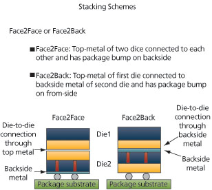
Having taken all these considerations into account, a designer will also have to look at the kind of 3D configuration that is to be used: face-to-face (F2F) or face-to-back (F2B) (Figure 5, p. 50).
Source: TSMC

FIGURE 5 Emerging SiP configurations
F2F is where the top metal layers of two dice are connected to each other and the packaging bumps are placed on the backside metal of one of the die. F2B is where the top metal of one die is connected to the backside of the second with bumps on the front. “F2F is probably the one that you will see first because it is easier to achieve whereas F2B involves a more complex copper-to-copper bonding,” says Quan. “F2F is an incremental step.”
Making it happen
“We’ve been talking about SiP for a few years, and things got very serious about three years ago,” says Quan. “Then the talk was of seeing this happen on a major scale in 2009, but it’s been pushed out and pushed out. It went to 2010, then to 2011, then to 2012. I think now that we’ll see something maybe in late 2010 but really in 2011 for 3D IC.” The issue, he says, has been demand. “It is technologically challenging, but you also need a number of clients who want to work this through.”
The same applies to TSMC’s relationships with EDA vendors and other suppliers into the Reference Flow ecosystem. “We’re manufacturing the wafer, but we need that collaboration, especially with the EDA guys, where they make sure that design tools are 3D-aware,” says Quan.
“Right now, we’re working with all the major vendors and a lot of the start-ups that are coming into this space because they can see that there are new challenges to address.
“I’ll give you an example of the problem. With some tools when you load up the design into the system, you have to point the software to a very specific technology file and that puts you back in the world of single SoC, single chip design. We need to make it so that you can now visualize a die on top of or underneath that. You need a schematic or a netlist to drive that. And then you can identify the connections between the two dice and perform the analysis.”
This is not a trivial task, and so vendors, like TSMC, have wanted to see that there is a market for enhancing their tools to do this. “They want to see, have to see a return on the investment. I think that now we are at the point where there is a significant number of customers who want to do this and have the resources to pay for it.”
Hence, SiP’s debut in Reference Flow 10. However, Quan does note that things are still at a very early stage. “If you go back to the beginning of what should be the process, somebody at the customer level has to make the high-level decision of whether to go SoC or SiP—or even, if they go SiP, whether to go for a newer 3D IC approach or a more traditional side-by-side approach,” says Quan.
“All that means that you need to know, early, the additional or comparative time, the relative cost and complexity, and the final yields, with and without TSV. And what I’ll say is that we are learning here. We have some preliminary numbers so far, and we have a customer who feels comfortable with taking things forward on this basis within the requirements of their system. And this is where we have to start. I’m confident we’ll build from here.”


