I3C specification updates I2C for sensor subsystems
Many applications use the I2C serial communication protocol to connect sensors due to its simple two-wire interface. As systems add sensors, designers need a better interconnect scheme, known as I3C, to keep up with their growing bandwidth requirements and the need to implement high-priority interrupt schemes.
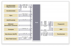
The issue is illustrated in Figure 1, an example of the variety of sensor interfaces used in typical multi-sensor systems.
Figure 1 A multi-interface based sensor system (Source: MIPI Alliance)
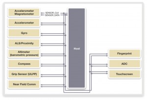
The MIPI Alliance is releasing I3C, a specification that incorporates attributes of I2C and SPI, as an alternative interface encompassing the benefits of these interfaces in one interface. I3C builds on the capabilities of I2C and the ecosystem that has grown up around it, while preserving the two-wire serial interface. Using I3C, system designers can easily connect more sensors, while reducing power consumption, component and implementation costs. Figure 2 shows an example I3C-based sensor system.
Figure 2 An I3C-based sensor system using an I3C bus (Source: MIPI Alliance)
The MIPI I3C specification is backward compatible with I2C, allowing I2C slave devices to exist on the same interface as devices using the I3C specification. The MIPI I3C specification provides in-band interrupts within the 2-wire interface, which reduces device pin count and signal paths.
I3C is a two-wire bus. Its SDA signal carries bidirectional serial data. Its SCL signal can act as either a clock pin, or as a data pin in high data-rate (HDR) applications. The I3C bus supports a mixture of message types including: I2C-like single data rate (SDR) messages which use SCL clock speeds of up to 12.5MHz, and HDR messages at higher data rates. The standard also supports slave-initiated in-band interrupt requests to the master, which can include requests to take the master role, enabling a dual-role master-slave IC capability. I3C also enables peer-to-peer communication between I3C slaves, which provides flexibility in system implementation.
The data rates supported on an I3C bus depend on the bus mode, the type of devices on the bus, and their capabilities.
A bus to which only I3C devices are connected is called a pure I3C bus, and supports speeds from 8.8 to 26.7Mbit/s. Typically, the SCL clock frequency in a pure I3C bus is 12.5MHz.
If the bus connects a mix of I2C and I3C devices, the I3C master can communicate to the I2C slaves at fast mode (FM) and fast mode plus (FM+) speeds, of up to 400Kbit/s or 1 Mbit/s, respectively. In a mixed-mode bus, the I3C master can still communicate to I3C slaves at up to 20.5Mbit/s. Connecting I2C devices to an I3C bus limits its operating speed to 20.5Mbit/s, instead of 26.7Mbit/s.
A pure I3C bus supports HDR and double-date-rate modes, multi-master support, dynamic addressing, command-code compatibility and a uniform approach for advanced power management features, such as sleep mode.
I3C bus configuration and device roles
The I3C standard defines five device roles:
- Main master, which controls the I3C bus and function, and includes bus ownership control and handoff to secondary masters.
- Secondary master, which takes temporary control of the I3C bus, needs permission from the main master, and passes control back to the main master once control tasks are exercised.
- Slave, which responds to either common or individual commands from the I3C master.
- Peer-to-peer slave, which can write to, or read from another slave without the interaction of the master.
- I2C slave, for legacy I2C devices present in an I3C bus, to which I3C master devices can communicate but whose speed and capabilities are constrained.
The MIPI I3C specification defines different responsibilities for each type of device, such as managing SDA arbitration, dynamic address assignment, hot-join features, HDR master and slave capability.
- SDA arbitration resolves bus ownership when multiple devices are transmitting at once. I3C uses the SDA line during the arbitration process and follows the common open-drain approach. The master typically manages the SDA arbitration.
- Dynamic address assignment: The I3C main master assigns each device a unique address, either when the bus is initialized or when a new device is connected to a configured I3C bus.
- Hot-join feature: Slaves don’t have to be activated when the I3C bus is powered up, and could be connected but not activated, or added later on. Activating such slaves is known as hot-join and enables the master to assign a dynamic address to the slave when it asks for one.
- HDR master and slave capability: Masters and slaves capable of supporting high-data-rates of 16.84Mbit/s and above are defined as HDR master/slave capable.
Some I3C use cases
Image sensors
Many systems use the MIPI Camera Serial Interface (CSI-2) protocol to connect to image sensors and the Camera Control Interface (CCI) for a side-band control channel, based on the I2C protocol. Replacing this sideband channel with I3C would simplify system implementation, since image sensors will be able to use I3C to communicate control information and to transmit image data in the future use case.
Sensor subsystems
An I3C master could be used to manage a set of sensors working at different speeds and in different modes as a sensor subsystem, with the master connecting to an SoC CPU through, for example, an ARM AMBA bus. Typical examples of such sensors are the touchpad sensor in a mobile device, gyroscopes, and camera interface, all of which use the I3C bus to communicate back to the CPU in the SoC.
Sensor hub
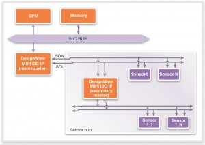
Figure 3 shows how an I3C interface could be used in a sensor hub. The I3C bus has a secondary master that acts as a hub, takes ownership of the I3C bus and communicates to the sensors directly. As soon as the secondary master has the relevant sensor data available on its I3C bus, it can communicate to the main master, which propagates the data to the CPU.
Figure 3 An I3C sensor hub use-case (Source: Synopsys)
Implementing I3C
The MIPI I3C specification combines features from I2C and SPI to provide a uniform standard and scalable interface to connect multiple sensors to the SoC with a low pin count and at low power. The MIPI Sensor Working Group, consisting of many major system design and ASIC vendors, has been jointly defining the I3C specification. Working with the ecosystem, Synopsys has implemented I3C controller IP and validated the specification to help create a uniform, scalable next-generation serial interface.
Further information
White Paper: High Performance and Scalable Sensor Connectivity with MIPI I3C
Author
Hezi Saar is a staff product marketing manager at Synopsys responsible for its DesignWare MIPI controller and PHY IP product line. He brings more than 16 years of experience in the semiconductor and electronics industries in embedded systems. Prior to joining Synopsys, he was responsible for advanced interface IP at Virage Logic, before it was acquired by Synopsys, and had also served as senior product marketing manager leading Actel’s Flash FPGA product lines. He holds a BS from Tel Aviv University in computer science and economics and an MBA from Columbia Southern University.


