Getting better results faster with a unified RTL-to-GDSII product
Complex SoCs need systemic optimisation to achieve best time to results, enabled by the use of a unified RTL-to-GDSII flow underpinned by a unified data model.
Each new silicon process node brings a huge jump in complexity. But, if you’re pushing the performance limits on a new process node, you have a particularly tough challenge on your hands. You used to be able to ignore many interactions as second- or third-order effects – but you can no longer do so. Those shortcuts are no longer available to you. As a result, the time it takes for you and your team to complete a high-performance design balloons with each generation. Margins are slim, process windows are tight, and there is simply no room for error in the final design.
Improvements to design tools help, and there are many small changes that can bring respite or temporary relief. But there are two significant changes that can transform both how the tools operate and how quickly a design can be completed. By using a unified single data model both in the early and late phases of the design, and by tightly integrating the engines that use that model, design time can be dramatically reduced. Beyond the traditional boundaries and silos innate in point-tool solutions – each with its own view and interpretation of the design process, a single RTL-to-GDSII solution with a single data model brings better results faster – by design.
The challenges of traditional flows
Of the factors constraining designers, one stands out: the time it takes to complete a design, which we call time-to-results, or TTR. It can take so long to get the design to converge that success is declared when the design results are merely “good enough.” There’s no time for improvement or optimization; any such changes would trigger a whole new set of full-flow tool runs and push completion out too far, risking a market-window miss. Engineers end up spending their time managing the tools to get adequate results rather than doing what engineers do best: playing with trade-offs to find the best possible solution.
This poor TTR comes from poor convergence across the wide range of point tools involved in a full end-to-end flow. Each tool does the best that it can, given the limited information that it has available to it, to produce a solution that best meets its own view of success. This is what point tools are required to do. When we place those pieces together in a flow, that “averaged success” often fails to converge and places stresses on later tools in the flow to make up the difference. All of these things conspire to increase overall time-to-results and leave engineers scratching their heads over which part of the flow to tweak to improve the overall system response.
These tools stresses additionally create instability that hurts overall closure convergence. When tools like synthesis engines are pushed to extremes, slight changes can be magnified to dramatically change final results. It’s hard to tweak results by tweaking the tools; the Butterfly Effect magnifies slight input changes to give very different output changes, making convergence a nightmare.
Two primary design phases
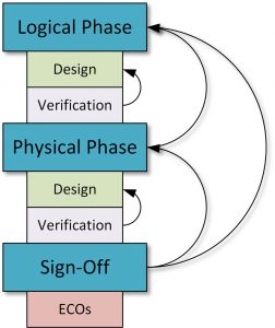
Traditional digital design flows work in two major phases: the logical and the physical. Work starts at a highly abstracted logical level, specifying high-level behaviors that the tools will render into logic. Tools use rough-and-ready estimates to complete their tasks more quickly. Work continues in this phase, iterating between design and verification, until performance, power, and area (PPA) have been closed.
Once the logical phase is complete, the physical phase begins. Here the abstracted elements specified in RTL are given physical embodiments: real transistors, real wires, and real passives – all on real silicon. Rather than the estimates used in the logical-phase models, the physical phase uses models tightly bound to physical realities. Tools are more accurate, but they are also slower to run.
As with the logical phase, here again we iterate between physical design and verification tools to get closure. If the numbers used in the logical phase were too inaccurate, then we may need to depart the physical phase and loop back into the logical phase to refine the logical design before returning to the physical design.
Once converged at the physical level, then the final design must be confirmed as manufacturable through exhaustive signoff tools that can run for days given the 200+ corners that must be covered for today’s process nodes. Mistakes found at this juncture can be expensive and time-consuming to fix – especially if small changes result in large circuit changes.
Figure 1 A traditional flow will lead to multiple point optimisations (Source: Synopsys)
Design time – the time spent doing real engineering where balances and trade-offs are down to the designer to optimize architectures – is squeezed because too many iterations are required within both the logical and physical phases, and there are too many iterations between the logical and physical phases. The logical phase knows nothing of the physical-phase data, and the physical phase knows nothing of the logical-phase data. And so TTR suffers.
There are two main reasons why convergence is such a tricky business in conventional flows.
- Data created by one tool and used by a subsequent tool is passed by file transfer. The first tool abstracts the wealth of data that might exist in memory in order to pass only the necessary pieces to the next tool. It’s a matter of efficiency and the fact that point tools must hand off specific file formats. That means that each tool has access only to the data passed to it in a file. There may be lots of other useful data that existed at some point, but if it’s not in the file, then it can’t be used to achieve better results downstream.
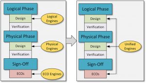
- Both the logical and physical phases have engines that provide convergence within their own phase. For example, a synthesis tool will have a timer, a parasitic estimator/extractor, or a placer with a legalizer, and a global router or congestion modeler. The physical-level placement and routing will have their own versions of such engines. But each set of tools has been created by a different team, each of which decides what data to abstract in the transfer files. Therefore, while they operate similarly, they don’t operate exactly alike. The differences can be a cause of additional iterations both within and between phases. Each set of tools, by itself, works well. It’s just that they’re challenged to work with each other.
Using a single data model
The first big step we can take is to use a single data model. Whether a logical or physical model, it’s available to all tools – logical and physical – at all times. That means that logical engines can take some cues from physical parameters to improve their results and similarly, physical tools can mine architectural and logical intent from early in the design process to deliver a better overall solution.
A particularly interesting case would be the early stages of the design process where we’re doing floorplanning or assessing overall design “implementability.” Having access to physical information for the target process means that we can create a better high-level layout – one that accounts for the physical characteristics of the process. This early layout will naturally be refined as we progress through the flow.
Another example would be that of clock synthesis. There are new techniques like concurrent-clock-and-data (CCD) optimization that are paramount in efficiently closing server-class Arm cores due to the Arm architecture, which relies on cycle borrowing across logical partitions. This can’t be done effectively without knowledge of the clock and data drivers to be used. That’s an example of physical data required during the logical phase. Without that specific data, the tools would have to make assumptions about the clock drivers’ potential and what topology it implied. If those assumptions turned out to be too far off, we’d have to go back and re-plan or even re-architect the entire CPU subsystem.
Integrate a common set of engines
By using the same engines for the logical and physical phases, we no longer have discrepancies between approaches, algorithms, and assumptions made. The engines used early in the design flow will be the same ones used to refine and close the design later on, relying on the same costing methodologies, the same optimization trajectories, and the same view of the entire dataset and how to best utilize it.
Note that this is very different from ‘unifying’ a flow by placing disparate tools under a single integrated design environment (IDE). The IDE does nothing to give full data access to all the tools, and it does nothing to ensure that a single set of engines is used. A unified flow may include an IDE, but it’s not the IDE that’s responsible for the improved TTR and PPA results.
Figure 2 A flow based on a unified data model will enable systemic optimisations (Source: Synopsys)
Unified models and flow drive better results
Design results from this approach are encouraging. As examples:
- A multi-million-instance design at the 7nm node achieved 10% lower leakage, 10% less total negative slack (TNS), up to 5% lower dynamic power, and up to 3% less area.
- Designs of 4-6 million instances, also on 7nm node, achieved 6-8% power savings and over 40% reduction in TTR.
- Blocks with 2-5 million instances on a 16nm node achieved worst negative slack (WNS) reduced by a third, and the total number of violating paths cut in half. Area dropped by over 10%, while the number of integrated clock gates and the number of inverters/buffers dropped significantly. TTR fell by 90%.
- Blocks with 2-7 million instances on a 28nm process had WNS and TNS drop by half, with area reduced by 10% and the number of standard-VT transistors dropping by 30% in exchange for 7% more power-saving high-VT transistors (pre-CTS).
- Designs from 5-10 million instances achieved from 22-37% power savings.
- An ECO operation went from 2 weeks to 1 day, reducing the number of ECO iterations from 12 to 0 – and resulting in over 2% fewer instances without degrading the quality of results.
Of course, some of the gains come from improvements to specific tools. But many of those improvements are possible specifically and only because the unified data model gives each engine access to everything.
Moving from a heterogeneous, federated set of data models to a single unified model, and using a single set of engines in a unified RTL-to-GDSII flow can have a significant impact on both TTR and PPA results. With access to all the data, algorithms can be made much more effective. With excellent correlation between logical and physical results, iterations can be dramatically reduced.
With less time spent on managing a design through a flow, we can reach market more quickly. Or we can spend more time optimizing results. And we may even be able to do both: get a more competitive product to market more quickly. Which, at the end of the day is what designers want to and should be doing.
Further information
More information is available here.
Authors
Shekhar Kapoor, director product marketing, and Mark Richards, senior technical marketing manager, Synopsys
Company info
Synopsys Corporate Headquarters 690 East Middlefield Road Mountain View, CA 94043 (650) 584-5000 (800) 541-7737 www.synopsys.comSign up for more
If this was useful to you, why not make sure you’re getting our regular digests of Tech Design Forum’s technical content? Register and receive our newsletter free.


