The impact of HDI and microvias on PCB design
 What impact do HDI via structures have on PCB design metrics? Andy Kowalewski describes a recent experiment.
A PCB’s density has traditionally been seen as a function of the trace and space geometry and the number of signal layers. Emerging technologies such as microvias and buildup fabrication may force us to rethink this formula. In this light, our company SyChip tested the effect of new blind and buried via structures on PCB size and density.
The test vehicle was a classic through-hole (TH) reference board (VIDAR).
Alternative stackups using blind and buried vias
Four commonplace approaches to the blind and buried via stackups were used. Each structure used the same traces, spaces, material types and thicknesses, to keep the impedances within specification. The boards’ sizes and layers were reduced to the smallest that could be 100% auto-routed and that the via structure would permit.

The test vehicles (TVs) were:
TV1: drilled sequential lamination
This is the only practical way to wire up a higher density board (i.e., one with an average pin count per square inch above 120) and not use microvias. The 12-layer multilayer stackup was composed of two 4-layer multilayers, drilled, plated and then laminated to two rigid cores with three pieces of prepreg. The board size has been reduced 23% to 313cm2 (50in2) and the drill size to a 0.2mm (0.008in) FHS for the composited multilayers but kept at a 0.25mm (0.010in) FHS for the THs.

TV2: staggered sequential microvia buildup
This staggered via IPC Type III stackup is the most popular and versatile technique. The 10-layer multilayer stackup was comprised of one buildup layer on each side of an 8-layer multilayer board, which was mechanical/laser drilled and plated, and then laminated to a piece of prepreg and foil. The board size has been reduced 30.8% to 281cm2 (45in2) and the microvia drill size is a 0.15mm (0.006in) FHS for the two buildup layers. The composite multilayer remains a 0.25mm (0.010in) FHS for the THs and buried vias.
TV3: stacked sequential microvia buildup
This stacked via IPC Type III stackup is becoming more popular in the US. The 8-layer multilayer stackup was composed of two buildup layers on each side of a 4-layer multilayer board, which was mechanical/laser drilled and plated, and then laminated twice to pieces of prepreg and foil. The board size has been reduced 43.1% to 231cm2 (37in2) and the microvia drill size is a 0.15mm (0.006in) FHS (but stacked) for the two buildup layers. The composite multilayer remains at a 0.25mm (0.010in) FHS for the THs and buried vias, but the microvias can be stacked on them.
TV4: co-laminated any-layer microvia buildup
The any-layer via is an IPC Type VI stackup, popular in Japan and Asia for its high density. The 8-layer multilayer stackup was composed of four double-sided layer pair cores. Each was mechanically or laser drilled and plated, etched, then tested. These were then laminated with prepreg that also has vias. This scheme allows any layer to connect to any other layer. The board size has been reduced 50.8% to 188cm2 (30in2) and the microvia drill size is a 0.15mm (0.006in) FHS but stacked. This stackup does not have any THs.
PCB basis
A 16-layer TH board was selected as the basis for the various strategies. It is dominated by a 1517-pin FPBGA with 50W single-ended drivers and 100W differential data pairs. Two other BGAs of 940 pins and 498 pins complicate the design. All BGAs were 1.0mm pitch. These are connected to 18 flash memories with 144 pins @ 0.8mm. The multilayer board is 25.4×19.8cm (10.0×7.8in) with a full 1.5V power plane and a 2.5V, 1.25V, 5V split power plane. The redesigned blind-buried via (and HDI) boards are 16.5×19.6cm (6.5×7.7in), 15.2×19.1cm (6.0×7.5in), 14.0×17.0cm (5.5×6.7in) and 12.7×15.2cm (5.0×6.0in). The 1517-pin device is now at 0.8mm pitch, the 940-pin BGA at 0.65mm and the 498-pin BGA at 0.5mm. All the flash memories are reduced to 0.5mm pitch devices.
Setting up HDI routing
Mentor Graphics’ Expedition EDA Tool was used. Setting up 21 different HDI architectures was straightforward. The three complex BGAs were fanned out semi-automatically using the unique blind/buried via available for that structure.
The auto-router was optimized for each type of blind/buried via structure and layer-pairing. Auto-routing was performed based on critical nets and buildup layers, then tuned and smoothed. After maximum utilization of blind vias, larger TH and buried vias were allowed.

Performance of microvias
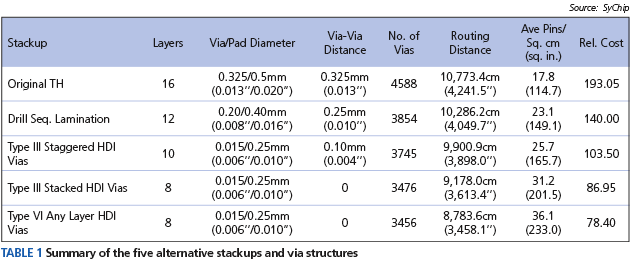
The results of the four design runs were remarkable. The via geometry, clearances and stackup had a profound effect on breakout and routing. These were the overriding variables that enabled the design of a smaller board with fewer layers. With fewer THs, innerlayer routing was 2-3X greater because of the additional space freed up by removal of the large drilled holes. The alternative stackups of the HDI boards also allowed microvias to replace 45% of the THs. The routing layer-pairs of X-Y using microvias as layer-transitions greatly reduced the need for buried vias and THs. The results are shown in Table 1.
THs vs. HDI structures
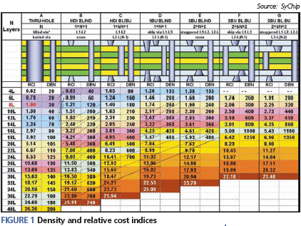
Figure 1 summarizes the positive effect blind and buried microvias have on board size, layers and density. Each main column represents a via architecture, and these are separated into two metrics: relative cost index (RCI) and density (DEN). Total layers separate the rows. The RCI metric is based on quotations and prices gathered for high-volume production globally. The DEN metric is based on the average number of component, connector and test pins (leads) on both sides of the board divided by the board’s length and width.
Conclusion
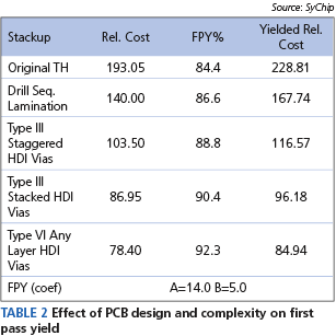
The results in Table 1 show the improvements that blind and buried vias provide in layer and size reduction. The relative costs are calculated by multiplying the relative cost index (RCI) by the board size. When the relative costs are divided by first pass yield, the results are seen in Table 2. TV1 is a 29.3% reduction in cost over the TH version, but TV2 is a 49.1% reduction, TV3 is a 58.0% reduction and TV4 is the largest with a 62.9% reduction.
Andy Kowalewski is PCB design manager at SyChip.
Since vias are plated with the platnig process, the thickness of the barrel will only be up to the thickness of the added platnig. Say that a 2oz finished board is 1oz start and plated up to be 2oz, then the vias will have only up to 1oz of copper thickness. The current rating for the via should be determined by using the thickness of the secondary platnig and be conservative.