Building reusable verification environments with OVM
This article reviews the reuse potential within the Open Verification Methodology, with special focus on four particularly fruitful areas: testbench architecture, testbench configuration control, sequences, and class factories.
Numerous methodologies are available to help engineers speed up the verification development process and make testbenches more efficient. Promoting reuse at sophisticated levels is becoming an increasingly important part of this landscape.
This article specifically reviews the reuse potential within the Open Verification Methodology (OVM), with special focus on four particularly fruitful areas: testbench architecture, testbench configuration control, sequences, and class factories. A simple router verification example, pw_router, illustrates schemes for building reusable OVM testbenches.
A testbench developed with reusability in mind will save a lot of duplicated effort and time. Testbench code reusability from block level to system level is also an immediate need for larger systems. Reusability from project to project is similarly desirable.
In recent years, various methodologies have emerged to help engineers speed up the verification development process and make testbenches more effi cient. The initial version of OVM includes features such as agents, virtual sequences, and transaction-level modeling (TLM) that directly promote intelligent reuse. Most advanced reuse techniques in OVM are similar to those found in the proven eRM/sVM methodology. Users and managers may not know exactly what SystemVerilog coupled with OVM offers in the area of reusability. Based on our experience in setting up OVM-based environments, we have identified key areas where users can extract major benefits in terms of testbench reusability. This paper discusses four of those in detail: testbench architecture, test bench configuration control, sequences and class factories. A simple router verification example, pw_router, will illustrate our schemes for building reusable OVM testbenches.
Testbench architecture
A key aspect of developing effi cient reusable verification code is a testbench architecture made up of multiple layers of highly confi gurable components. This section describes how unit-level and system-level testbenches are built into multiple layers and highlights component reusability. Complex designs are typically broken up into multiple manageable and controllable unit-level testbenches and a system-level testbench that takes in the entire design. Therefore, reuse of components across multiple unit-level testbenches and at the system level is vital. OVM promotes a layered architecture that consists of a testbench container and two verification components types: interface components and module/system components.
Interface components
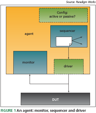
These are reusable verification components specifi c to a particular protocol. They comprise of one or more ‘agents,’ an agent being a component that connects to a port on the DUT. It is made up of a monitor, sequencer, and a driver (Figure 1). The testbench can confi gure the agent as either active or passive.
In active mode, the agent builds the sequencer, driver and monitor. In this configuration, stimulus is driven onto the bus via the sequencer/driver and the monitor captures bus.
activity. In passive mode, the agent includes only a monitor – the sequencer and driver are not included inside the agent. A passive agent only captures bus activity and it does not drive stimulus into the DUT.
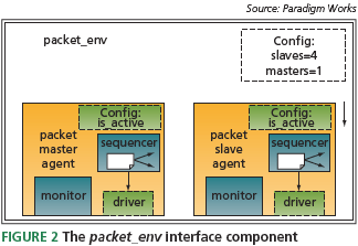
The topology of the pw_router DUT consisted of one input port and four output ports. For our testbench, we developed an interface verification component called packet_env. The packet_env includes one master agent and four slave agents (Figure 2). The master agent is connected to the input port and the slave agents are connected to the output ports.
Module components
These are reusable verification components for verifying a DUT module. Module components promote reuse for multiple testbenches – they may be reused in both a unit-level testbench and a system-level testbench.
Module components encapsulate multiple interface components and monitor activity among the interfaces. The monitor typically observes abstract data activity such as registers and memory contents. Also, a module component undertakes scoreboarding to verify end-toend expected data against actual data. Occasionally, a module component may include a virtual sequence that coordinates stimulus activity among multiple interface components.
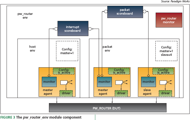
The pw_router’s testbench’s module component is shown in Figure 3. It consists of two interface components: packet_ env and host_env, an interface component. There are two scoreboards: packet scoreboard and interrupt scoreboard. Finally, the pw_router module component contains pw_router monitor, a monitor that shadows the contents of the registers/ memories inside the design. The scoreboards connect to host_env and packet_env’s monitors via TLM ‘analysis ports’. These ports allow transactions to be sent from a producer (publisher) to one or more target components (subscribers). TLM promotes component reuse in a number of ways. Its use of transactions eliminates the need for testbench-specifi c component references (pointers) within other components. There is a standard, proven interface API for sending/receiving transactions. The transactions’ abstraction level may vary, but at the product-description rather than the physicalwire level.
The unit-level testbench
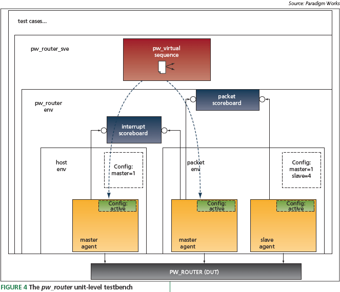
The unit-level testbench for pw_router is shown in Figure 4. The pw_router_sve and test cases are two additional container layers specifi c to this testbench. The pw_router_ sve container encapsulates the pw_router_env module component and other components not intended for reuse. For example, the pw_router virtual sequence component is included in the pw_router_sve container. This sequence coordinates host and packet stimulus. The test layer allows users (or test writers) the opportunity to customize testbench control.
System-level testbench
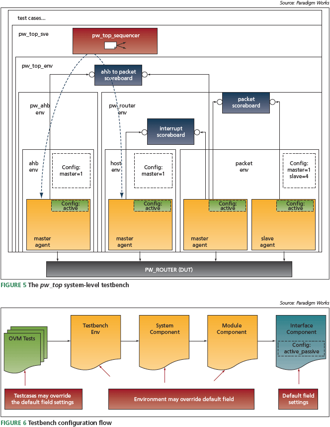
Figure 5 shows the system-level testbench for the pw_top design module. This design encapsulates pwr_router and another design module called pw_ahb. The system testbench for the pw_top design includes a top-level container called pw_top_sve and a system component called pw_top. A system component encapsulates a cluster of module components, performs scoreboarding, and may monitor activity amongst the module components. A system module allows for further reuse (e.g., pw_top may be included as module component in a larger system context). The pw_top system component includes and reuses the pw_route module component. In addition, a pw_top module component also encapsulates another module component called pw_ahb_env. Finally, a scoreboard laycomponent is included inside the system container to
verify the interface across the pw_ahb and pwr_router designs. The top-level pw_top_sve container encapsulates the system module pw_top and includes the sequencer component pw_top that is specifi c to the system-level testbench. This sequencer is responsible for coordinating AMBA bus (ahb) and host traffic at the system level.
In the system-level testbench, the packet master is confi gured as a passive agent. Because this is an internal interface inside the pw_system design, the testbench can monitor the interface but cannot drive data onto it. Note that putting the agent in passive mode does not affect the pw_router_env’s packet and interrupt scoreboards. They still verify expected data against actual data as they did in the unit-level testbenches.
configuration control
OVM components are self-contained. The behavior and implementation are independent of the overall testbench, facilitating component reuse. Typically, components operate with a variety of different modes controlled by fields (sometimes referred to as ‘knobs’). It is pertinent that the testbench environment and/or the test writers have the ability to configure component field settings. OVM provides advanced capabilities for controlling the configuration of fields. Examples include hierarchy fields such as the active_passive field inside an agent and behavior fields that may control testbench activities for, say, the number of packets to generate. The primary purpose of the configuration mechanism is to control the setting of field values during the build phase. The build phase occurs before any simulation time is advanced. The configuration mechanism gives test writers and higher layer testbench components the ability to overwrite the default field settings in the components. A testbench hierarchy is established in top-down fashion where parent components are built before their child components (Figure 6). Higher-level testbench layers (test cases and containers) and components (system/ module components) can therefore overwrite default configuration settings that govern the testbench hierarchy and its behavior.
OVM sequence mechanism
OVM sequences allow test writers to control and generate stimulus to the DUT. The sequence mechanism may be fl at, layered, hierarchical (sometimes referred to as ‘nested’), layered, and controlled from higher layers of abstraction using a mechanism called virtual sequences. All these sequence capabilities promote reuse.
An OVM sequence mechanism has three entities: a sequence or sequences, a sequencer and a driver.
A sequence is a construct that generates and drives transfers (or sequence items) to a driver via a sequencer. This type of sequence is referred to as a fl at sequence. Additionally, sequences can call other sequences – this is called a hierarchical sequence. Hierarchical sequences allow testbench developers to write new sequences that reuse other sequences. The sequencer is a verification component that mediates the generation and flow of data between the sequence(s) and the driver. The sequencer has a collection of sequences associated with it called a sequence library. The driver is a verification component that connects to the DUT’s pin-level interface. A driver includes one or more transaction-level interfaces that decode the transaction and drive it onto the DUT’s interface. The driver is responsible for pulling transactions from the sequencer and driving them onto the DUT’s pin interface. The sequencer and driver communicate through a special TLM consumer/producer interface. The TLM interface allows a single sequencer to be reused with different drivers.
A virtual sequence allows stimuli to be managed across multiple sequencers. For example, the design requires the host to initialize the DUT before routing packet traffic. Moreover, while packet_env’s sequencer has packet traffic flowing, the host_env’s sequencer needs to service interrupts. OVM virtual sequences provide the coordination needed here. Virtual sequences allow sequencers to be reused in different testbenches. For example, the testbench’s unit level and system level reuse the packet_env’s slave agent sequencer and host_env’s master sequence.
OVM class factory
The OVM class factory is a powerful mechanism that allows test writers to override the default behavior exhibited in the testbench. The class factory and configuration mechanism can both override testbench behavior but have different charters. The configuration mechanism’s primary focus is to give the testbench hierarchy an opportunity to overwrite default fi elds values in a top-down manner during the testbench’s build phase. The class factory gives users the ability to override OVM objects during the build and run phases.
An OVM class factory is a static singleton object. When OVM objects are created in the testbench, they may be registered into the class factory. Test writers can derive their own OVM objects and then perform type or instance overrides of the OVM objects in the testbench environment. This methodology is completely non-intrusive with regard to the testbench code. The test writers may change the behavior of an OVM object by overwriting virtual functions, adding properties, defi ning and adding additional constraints. This reduces the time to develop specifi c tests using a single verification environment and promotes reuse across multiple projects.
Conclusion
Upfront planning and knowledge of methodological best practice are crucial to the development of efficient OVM reusable code. It is important to plan all OVM testbench architectures early in the verification effort, before any code is implemented. When putting together testbench architectures, one must consider system-level and future project reuse. As noted in this article, OVM has features that greatly help with reuse such as the configuration mechanism, class factories, TLMs and sequences. The OVM best practice reuse capabilities will not become fully apparent just from reading the OVM Reference Manual, monitoring the OVM Forum, or looking through the OVM Examples. At time of writing (September 2008), it is only a little more than six months since the initial OVM release, so new material is starting to become available to aid users in developing reusable testbenches, and these releases need to be monitored carefully.
Paradigm Works
300 Brickstone Square
Suite 104
Andover
MA 01810
USA
T: +1 978 824 1400
W: www.paradigm-works.com


