Which ADC architecture is right for your application – Part One
Introduction
Selecting the proper ADC can appear a formidable task, considering the thousands on the market. A direct approach is to go to the selection guides and parametric search engines. Enter the sampling rate, resolution, power supply voltage, and other properties. Click ‘find’. And hope for the best. But it’s usually not enough. How does one deal with a multiplicity of ‘best choices’? Can one approach the task with greater understanding — particularly of the main architectures — and get better results?
Most ADC applications can be classified into four broad market segments:
(a) data acquisition
(b) precision industrial measurement
(c) voiceband and audio
(d) “high speed” (implying sampling rates greater than 5MSPS).
A very large percentage can be filled by successive-approximation (SAR), sigma-delta (∑-Δ), and pipelined ADCs. Figure 1 shows in a general way how these application segments and the associated typical architectures relate to ADC resolution (vertical axis) and sampling rate (horizontal axis). The dashed lines represent the approximate state-of-the-art in mid-2005. Even though the various architectures have specifications with a good deal of overlap, applications are key to making the right choice.
In this, the first part of a two-part article, we shall concentrate on increasing understanding of SAR ADCs for data acquistion, and sigma-delta ADCs for precision measurement and instrumentation. The second part considers sigma-delta ADCs for voiceband and audio and pipelined ADCs in ‘high speed’ applications.
Successive-approximation ADCs for data acquisition
From the modular and hybrid devices of the 1970s to today’s modern low-power ICs, the SAR ADC has been the workhorse of data-acquisition systems.
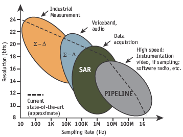
Figure 1. ADC architectures, applications, resolution, and sampling rates.
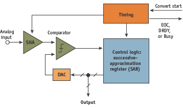
Figure 2. Basic successive-approximation (SAR) ADC.
Modern SAR ADCs are available in resolutions from 8 to 18 bits, with sampling rates up to several megahertz. State-of-the-art performance for available devices is 16bit at 3MSPS and 18bits at 2MSPS. Output data is generally provided via a standard serial interface (I2C or SPI, for example), but some devices are available with parallel outputs.
The basic architecture is shown in Figure 2. In order to process rapidly changing signals, SAR ADCs have an input sample-and-hold (SHA) to keep the signal constant during the conversion cycle. The conversion starts with the internal D/A converter (DAC) set to midscale. The comparator determines whether the SHA output is greater or less than the DAC output, and the result (the most-significant bit (MSB) of the conversion) is stored in the successive-approximation register (SAR) as a 1 or 0. The DAC is then set either to 1/4 or 3/4 scale (depending on the MSB’s value), and the comparator makes the decision for the second bit of the conversion. The result is stored in the register, and the process continues until all the bit values have been determined. At the end of the conversion process, a logic signal (EOC, DRDY, BUSY, etc.) is asserted. (Note that, as outlined above, the acronym SAR actually stands for successive-approximation register — the logic block that controls the conversion process.
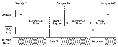
Figure 3. Simplified timing diagram of a SAR A/D converter.
The timing diagram for a typical SAR ADC is shown in Figure 3. The functions shown are present in most SAR ADCs, but their exact labels can differ. Note that the data corresponding to that specific sample is available at the end of the conversion time, with no ‘pipeline’ delay or ‘latency’. This makes the SAR ADC easy to use in single-shot, burst-mode, and multiplexed applications. The internal conversion process of most modern IC SAR ADCs is controlled by a high-speed clock (internal or external, depending on the ADC) that does not need to be synchronized to the CONVERT START input.
The basic algorithm used in the successive-approximation ADC conversion process can be traced back to a mathematical puzzle from the 1500s. The objective was to determine the least number of weights which would serve to weigh an integral number of pounds from 1 lb to 40 lb using a balance scale. One solution put forth by the mathematician Tartaglia in 1556, was to use the binary series of weights 1lb, 2lb, 4lb, 8lb, 16lb, and 32lb (or 20, 21, 22, 23, 24, and 25). (That this solution will actually measure unknown weights up to 63lb (26 – 1) rather than just 40lb). The binary algorithm, using a balance scale, is shown in Figure 4.
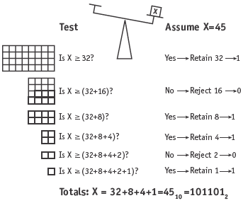
Figure 4. Successive-approximation ADC algorithm using balance scale and binary weights.
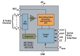
Figure 5. Functional block diagram of a modern 1-MSPS SAR ADC with 8-channel input multiplexer.
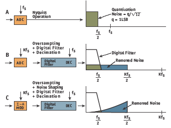
Figure 6. Noise-spectrum effects of the fundamental concepts used in ∑-Δ: oversampling, digital filtering, noise shaping, and decimation.
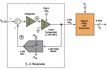
Figure 7. First-order sigma-delta ADC.
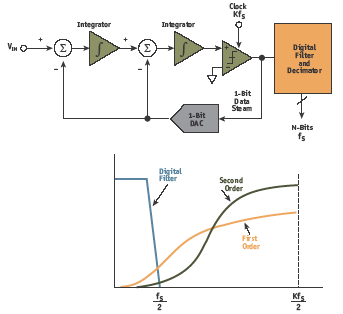
Figure 8. Second-order ∑-Δ modulator.
The overall accuracy and linearity of the SAR ADC is determined primarily by the internal DAC’s characteristics. Early precision SAR ADCs used DACs with laser-trimmed thinfilm resistors to achieve desired accuracy and linearity. However, this adds cost, and resistor values may be affected when the device undergoes packaging.
For these reasons, switched-capacitor (or charge-redistribution) DACs have become popular in CMOS-based SAR ADCs. The principal advantage here is that accuracy and linearity are primarily determined by high-accuracy photolithography, which establishes the capacitor plate area, hence the capacitance and the degree of matching. In addition, small capacitors can be placed in parallel with the main capacitors to achieve high accuracy and linearity without thinfilm laser trimming. Because temperature tracking between the capacitors can be better than 1 ppm/°C, a high degree of temperature stability is achieved.
CMOS, the process of choice for modern SAR ADCs, is also ideal for analog switches. Therefore, input multiplexing can be added to the basic SAR ADC function relatively straightforwardly, allowing integration of a complete data-acquisition system on a single chip. Additional digital functions are also easy to add to SAR-based ADCs. Figure 5 illustrates the elements of the AD79x8 series of 1MSPS SAR ADCs. The sequencer allows automatic conversion of the selected channels, or channels can be addressed individually if desired. Data is transferred via the serial port. SAR ADCs are popular for multichannel data-acquisition because they lack the ‘pipeline’ delays typical in ∑-Δ and pipelined ADC architectures. Sigma-delta ADCs for measurement and instrumentation Modern ∑-Δ ADCs have virtually replaced the integrating-type ADCs (dual-slope, triple-slope, quad-slope, etc.) for applications requiring high resolution (16 to 24bit) and effective sampling rates up to a few hundred hertz.High resolution, together with on-chip programmablegain amplifiers (PGAs), allows the small output voltages of sensors — such as weigh scales and thermocouples — to be digitized directly. Proper selection of sampling rate and digital filter bandwidth also yields excellent rejection of 50Hz and 60Hz power-line frequencies. ∑-Δ ADCs offer an attractive alternative to traditional approaches using an instrumentation amplifier (in-amp) and a SAR ADC. The basic concepts behind the ∑-Δ ADC originated at Bell Labs in the 1950s and by the late 1960s, the architecture was well understood. However, because digital filters (then a rarity) were an integral part, practical IC implementations did not appear until the late 1980s, when signal processing in digital CMOS became widely available. The basic concepts used in ∑-Δ are oversampling, noise shaping, digital filtering, and decimation (Figure 6).
Figure 6A shows a noise spectrum for traditional Nyquist operation, where the ADC input signal falls between dc and fS/2, and the quantization noise is uniformly spread over the same bandwidth. In Figure 6B, the sampling frequency has been increased by a factor, K (the oversampling ratio), but the input signal bandwidth is unchanged. The quantization noise falling outside the signal bandwidth is then removed with a digital filter. The output data rate can now be reduced (decimated) back to the original sampling rate, fS. This process of oversampling, followed by digital filtering and decimation, increases the SNR within the Nyquist bandwidth (dc to fS/2). For each doubling of K, the SNR within the dcto- fS/2 bandwidth increases by 3dB. Figure 6C shows the basic ∑-Δ architecture, where the traditional ADC is replaced by a ∑-Δ modulator. The effect of the modulator is to shape the quantization noise so that most occurs outside the bandwidth of interest, thereby greatly increasing the SNR in the dc-to-fS/2 region.
The basic first-order ∑-Δ ADC is shown in Figure 7, with the ∑-Δ modulator shown in some detail. The heart of this basic modulator is a 1bit ADC (comparator) and a 1bit DAC (switch). Although there are a number of multibit ∑-Δ ADCs, those using the single-bit modulator boast inherently excellent differential linearity.
The output of the modulator is a 1bit stream of data. Because of negative feedback around the integrator, the average value of the signal at B must equal VIN. If VIN is zero (i.e., midscale), there are an equal number of 1s and 0s in the output data stream. As the input signal goes more positive, the number of 1s increases, and the number of 0s decreases. Likewise, as the input signal goes more negative, the number of 1s decreases, and the number of 0s increases. The ratio of the 1s in the output stream to the total number of samples in the same interval — the ‘ones density’ — must therefore be proportional to the dc value of the input.
The modulator also accomplishes the noise-shaping function by acting as a low-pass filter for the signal and a high-pass filter for the quantization noise. Note that the digital filter is an integral part of the ∑-Δ ADC, and it can be optimized to give excellent 50Hz/60Hz power-frequency rejection. However, the digital filter does introduce inherent pipeline delay, which must be considered in multiplexed and servo applications. If signals are multiplexed into a ∑-Δ ADC, the digital filter must settle to the new value before the output data is valid. Several output clock cycles are generally required for this settling. Due to the pipeline delay of the digital filter, the ∑-Δ converter cannot be operated in a ‘single-shot’ or ‘burst’mode. Although the simple first-order single-bit ∑-Δ ADC is inherently linear and monotonic because of the 1bit ADC and 1bit DAC, it does not provide sufficient noise shaping for high-resolution applications.
Increasing the number of integrators in the modulator
(similar to adding poles to a filter) provides more noise shaping at the expense of a more complex design — as shown in Figure 8 for a second-order 1bit modulator. Note the improvement in the noise shaping characteristic compared to a first-order modulator. Higherorder modulators (greater than third order) are difficult to stabilize and present significant design challenges.
A popular alternative to higher-order modulators is to use a multibit architecture, where the 1bit ADC (comparator) is replaced with an Nbit flash converter, and the single-bit DAC (switch) is replaced with a highly linear Nbit DAC. Expensive laser trimming in multibit ∑-Δ ADCs can be avoided by using techniques such as data scrambling to achieve the required linearity of the internal ADC and DAC.
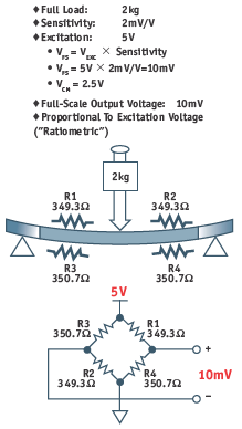
Figure 9. Load-cell signal-conditioning application.
While integrating architectures are still used in applications such as digital voltmeters, the CMOS ∑-Δ ADC is the dominant converter for today’s industrial measurement applications. These converters offer excellent power-line common-mode rejection and resolutions up to 24 bits as well as digital conveniences such as on-chip calibration.Many have programmable-gain amplifiers (PGAs), which allow small signals from bridge- and thermocouple transducers to be directly digitized without additional external signal conditioning circuits and in-amps.
Figure 9 shows a simplified diagram of a precision load cell which produces 10mV full-scale output voltage for a load of 2kg with 5V excitation. The bridge’s common-mode output voltage is 2.5V. The diagram shows the bridge resistance values for a 2kg load. The output voltage for any given load is directly proportional to the excitation voltage, i.e., it is ratiometric with the supply voltage.
A traditional approach to digitizing this low-level output would be to use an instrumentation amplifier to provide the gain to drive a conventional SAR ADC of 14 to 18bit resolution. Because of offset and drift considerations, an ‘auto-zero’ in-amp is required. Filtering circuitry is needed due to the noise of the auto-zero in-amp. In addition, the output data from the SAR ADC is often averaged for further noise reduction.
An attractive alternative to the traditional in-amp/SAR ADC approach is shown in Figure 10, which uses a direct connection between the load cell and the AD7799 high resolution ∑-Δ ADC. The full-scale bridge output of 10mV is digitized to approximately 16 ‘noise-free’ bits by the ADC at a throughput rate of 4.7Hz. Ratiometric operation eliminates the need for a precision voltage reference.
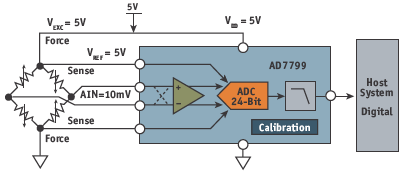
Figure 10. Load-cell signal conditioning using the AD7799 ∑-Δ ADC.
The ∑-Δ ADC is an attractive alternative when very low-level signals must be digitized to high resolution, but the user should understand that it is more digitally intensive than the SAR ADC and may therefore require a longer development cycle. Evaluation boards and software can help greatly. Nevertheless, there are many instrumentation and sensor signal-conditioning applications that can be efficiently solved with a traditional in-amp (for signal amplification and common- mode rejection) followed by a multiplexer and a SAR ADC.
Conclusion
We have still to consider ∑-Δ ADCs for voiceband and audio and pipelined ADCs in high-speed applications but it is already worth noting that the use of manufacturers’ selection guides and parametric search engines, coupled with a fundamental knowledge of the basic architectures, will help the designer select the proper ADC.
The use of manufacturers’ evaluation boards makes the process much easier. The Analog Devices’ ADIsimADC program allows the customer to evaluate the dynamic performance of the ADC without the need for any hardware. The required software and the ADC models (and many other analog and digital design aids) are free downloads at www.analog.com. This tool can be extremely valuable in the selection process.
Not to be overlooked is the proper design of the ADC input-, output-, and sampling-clock circuitry. Data sheets and application notes should be consulted. Finally, and equally critical to achieving a successful mixed-signal design, are layout, grounding, and decoupling.


