Pushing USB 2.0 to the limit
USB offers many advantages for use on embedded systems, although software developers remain concerned about the additional complexity it can bring to an application. For example, software drivers for SPI, RS-232 and other traditional serial protocols typically involve little more than read and write routines, while USB software drivers can span thousands of lines, incorporating routines that are difficult to develop and to debug. The software that sits on top of the drivers can be equally complex.
To avoid being forced to address enumeration and other confusing aspects of USB, many engineers turn to commercial off-the-shelf (COTS) USB software. For a developer using a reliable, well-tested software module, USB communication simply becomes a series of calls to easily understandable API functions. Thus, programmers who rely on such modules can afford their end-users the convenience of USB without significantly lengthening product development times. Using COTS USB software also offers the best guarantee that devices can interoperate, interconnect and/or communicate with one another as specified by the USB standard.
The Universal Serial Bus (USB) revolutionized the PC world and is rapidly gaining ground in the embedded controls market. The basis of its success is simplicity, reliability and ease-of-use.
In the PC world, USB has completely replaced the UART, PS2 and IEEE-1284 parallel ports with a single interface type, greatly simplifying software drivers and reducing the real estate that must be dedicated to bulky connectors. The rapid drop in solid state memory prices combined with the increased speed of the USB 2.0 specification (480Mbps) created the opportunity to store several gigabytes of data in USB memory sticks very quickly. As a result, memory sticks have replaced floppy disks and CD drives as the primary vehicle for data storage and transfer.
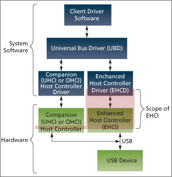
One further key to USB’s success is interoperability, based on the well-defined standard (Figure 1) and guaranteed by the USB Consortium. Any USB-certified device from any vendor will work in a plug-and-play fashion with any other USB-certified device from any other vendor. Multiple devices can operate on the same bus without affecting each other. The end-user no longer needs to specify IRQs for every peripheral in the system. The USB standard does all the housekeeping.
Another major advantage of USB is that it relieves system designers of the burden of implementing one-off interfaces and drivers that are incompatible and often unreliable. For users of embedded controls systems in particular, USB obviates the need to maintain an inventory of different, bulky cables as well as any concerns over their long-term availability because of the drop-in replacement nature of USB peripherals.
All these advantages have fostered the adoption of USB in the embedded space. It has become so popular that virtually every vendor of 32-bit flash MCUs offers several derivatives with USB full-speed device or On-The-Go (OTG) capabilities. Embedded microprocessors frequently include both high-speed device and host ports. Some even have an integrated USB hub that supports the connection of multiple USB devices, going some way beyond the initial line-up of keyboards, mice and storage card readers.
Source: USB Consortium

FIGURE 1 USB 2.0
The simplicity and ease-of-use of USB software and its high sustainable data rates are driving many designers to migrate designs to USB-enabled 32-bit MCUs, which are now price-competitive with 8- and 16-bit devices and offer higher internal bandwidth to handle and process hundreds of thousands of bits for each attached high-speed peripheral.
USB also offers the opportunity to replace wires between PCBs within a system (e.g., a host processor platform connection to a user interface panel). In most cases, the technology brings together different PCBs that do not sit close together. The USB cable is a robust, low-cost and EMI-tolerant alternative to parallel wires.
As USB has found its way into an increasing number of embedded devices, software developers have become wary of the additional complexity that this protocol can bring to an application. The developers of USB-enabled products must shoulder a hefty burden in order to grant end-users the convenience that has made this means of serial communication so popular. Whereas software drivers for SPI,
RS-232 and other simple serial protocols typically involve little more than read and write routines, USB software drivers can span thousands of lines, incorporating routines that are difficult to develop and to debug. The software that sits on top of the drivers can be similarly complex, in part because this code must manage enumeration, the byzantine process by which USB hosts identify devices.
In order to avoid concerning themselves with enumeration and other confusing aspects of USB, many engineers turn to commercial off-the-shelf (COTS) USB software. For a developer using a reliable, well-tested software module, USB communication simply becomes a series of calls to easily understandable API functions. Thus, programmers who rely on such modules can afford their end-users the convenience of USB without significantly lengthening product development times. Using COTS USB software also offers the best guarantee that devices can interoperate, interconnect and/or communicate with one another as specified by the USB standard.
Software solutions for USB implementations
For the sake of simplicity, ease-of-use and software portability, three hardware/software interface standards have been defined by Intel for the register level interface and memory data structures for the Host Controller hardware implementation: the Universal Host Controller Interface (UHCI) for low-speed, Open HCI (OHCI) for full-speed, and Enhanced HCI (EHCI) for high-speed USB host controllers.
The USB driver abstracts the details for the particular host controller driver for a particular operating system. On top of the driver, multiple client drivers run specific classes of devices. Examples of device classes are Human Interface Device (HID), Communication Device Class (CDC) and Storage Class.
Developers whose products function as USB hosts are not the only engineers who can benefit from a quality USB software module; implementers of USB OTG and devices also have much to gain. Although the makers of USB devices are somewhat insulated from the aforementioned host controller differences, these developers still must ensure that high-speed hosts can actually recognize their devices. A home-grown USB device implementation capable of full-speed communication must normally be overhauled to support high-speed communication. Even if the underlying USB device controller is capable of high-speed communication, the upper-layer software might not support the additional enumeration steps that high-speed communication involves. The upper layers of a solid COTS implementation, however, are intended to be used with any type of host, full- or high-speed.
Because hardware-related issues for both hosts and devices are minimized by USB software modules, overhead can be a major concern for developers considering these modules. Although most embedded microcontrollers cannot maintain high-speed USB’s 480Mbps maximum data rate, a low-overhead software module can ensure that rates well over the full-speed maximum of 12Mbps are viable.
Because these modules rely heavily on DMA for transferring packets to and from memory, applications that incorporate them are not forced to waste CPU cycles copying data.
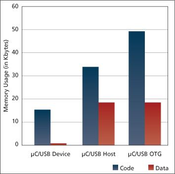
Source: Micrium

FIGURE 2 Memory footprint of USB modules
Of course, a low-overhead software module should use both memory and CPU clock cycles efficiently. The best commercial off-the-shelf (COTS) USB solutions are devoid of redundant code and superfluous data structures that would otherwise bring about bloated memory footprints. Given the magnitude of the USB protocol, the compact size of these modules is particularly impressive. For example, the code size of a normal configuration of Micriµm’s µC/USB-Host is just 35 kilobytes, while µC/USB-Device, which is Micriµm’s USB Device stack, has a code size of only 15 kilobytes. These modules’ memory needs, as well as those of Micriµm’s OTG module, µC/USB-OTG, are summarized in the graph in Figure 2.
The benefits that an expertly crafted USB module offers easily outweigh the small sacrifices necessary to accommodate such a module. Although developing a high-speed USB host or device without one of these modules is not impossible, it is hardly advisable. With a capable COTS solution on their side, astute engineers can accelerate the transition from full speed to high speed and can quickly move their USB-enabled products to market.
Hardware implications in sustaining high-speed USB bandwidth
Most USB-enabled MCUs are limited to 12Mbps full-speed USB 2.0. The problem here is that the amount of data being collected, stored and ultimately offloaded to a storage device for remote processing for today’s embedded controls applications has increased exponentially. Full-speed USB does not compete effectively with 20Mbps SPI or 100Mbps-plus parallel bus. Fortunately, flash MCUs and embedded MPUs are coming to market with on-chip 480Mbps high-speed USB 2.0. These chips are likely to speed up the adoption of USB for the majority of interconnects between PCBs as well as between the embedded system and its peripherals.
It is a relatively straightforward task to sustain a 480Mbps data rate in a PC or a 400MHz ARM9-based product running a Microsoft or Linux OS with a single memory space connected to a single high-speed bus. Achieving this on an ARM Cortex M3 flash MCU with a clock frequency of 96MHz is another story. To run at that speed, store the data in external or internal memory, process it and then resend it either over the USB link or another equivalent speed interface (e.g., an SDCard/SDIO or MMC), needs a highly parallel architecture where DMAs stream data without CPU intervention between memories and peripherals, and where the CPU has parallel access to its memory space to process the data.
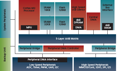
Source: Atmel

FIGURE 3 Block diagram of the SAM3 with multi-layer bus, DMAs and high-speed interfaces (HSMCI, EBI)
Atmel solved this problem on the SAM3U Cortex M3 Flash Microcontroller with a high-speed USB interface by adapting the multi-layer bus architecture of their ARM9 MPUs to the Cortex M3 and dividing the memory in multiple blocks distributed in the architecture.
Three types of DMAs are connected to minimize the loading of any data transfer on the bus and memories, and free the processor for the data processing and system control tasks.
Ideally, the central DMA features a built-in FIFO for increased tolerance to bus latency and programmable length burst transfers that optimize the average number of clock cycles per transfer, scatter, gather and linked list operations. It can be programmed for memory-to-memory transfers or memory-to-peripheral like a high-speed SPI or SDIO/SD/MMC Media Card Interface (MCI). The high-speed DMA used for the USB High-Speed Device (HSD) interface has a dedicated layer in the bus matrix, maximizing parallel data transfers. The risk of waiting for the bus availability has been removed, and the only critical access the programmer needs to manage is the access to the multiple memory blocks. Simultaneous accesses need to be avoided, otherwise a FIFO overrun or underrun can occur and data will be lost or the transfer will be stalled.
The peripheral DMA should be tightly integrated in the peripheral programmer’s interface, which will simplify peripheral driver development. It should have a reduced gate count to generalize its implementation without a serious cost adder reducing processor overhead in data transfers. Gate count reduction can be achieved by removing local storage capabilities and reducing linked list support to two memory areas.
Multiple data memory blocks should be distributed in the microcontroller. For example, two central SRAM blocks can allow the CPU to run from one with the DMAs loading and storing in parallel from the other. There should be several FIFOs built into the high-speed peripherals and DMA controller, including a 4KB DPRAM in the USB HSD interface. These memories reduce the impact of the bus or memory latency on the high-speed transfer. The programmer can allocate the 4KB DPRAM in the USB HSD to the different end points, except for the control end point since its data rate is low. Up to three buffers can be allocated to a single end point to support micro-chain messages.
Source: Atmel/Micrium
|
Mode |
Max bandwidth |
|
Bulk |
53.24MB/s |
|
Interrupt |
49.15MB/s |
|
Isochronous |
49.15MB/s |
|
Control |
15.87MB/s |
TABLE 1 Effective data rates for USB HS operating modes
Table 1 provides benchmark data on the effective data rates for the different operating modes of the USB HS Interface in Atmel’s Cortex M3-based SAM3U. The data is streamed in parallel to the processor doing the data packing or unpacking. The delta between the effective data rate and the maximum 480Mbps or 60MBs in Bulk, Interrupt and Isochronous modes, are due to the protocol overhead and not to any architectural limits.
The gap between the data requirements of embedded systems and the hardware that moves and processes that data has been growing exponentially in recent years. Recent developments in both microcontrollers and software capable of supporting high-speed USB provide a much needed solution. In the early stages of adoption, the majority of users are unlikely to run at the maximum 480 Mbps data rate. More likely, they will run at tens or hundreds of Mbps, to escape the limitations of full speed USB (12Mbps) or SPI (tens of Mbps). However, over time, data requirements will continue to grow and thereby push demands on any system.
Running at the maximum 480 Mbps data rate on a Cortex M3 class flash MCU is feasible through a careful design of the internal bus, memory and DMA architecture. Using COTS software takes the burden and risk away for the software developer, providing the best guarantee for USB compliance and interoperability in the minimum amount of time. The use of market-standard implementations of the USB host interface defined by Intel increases the choice in OSs, RTOSs.
Micrium
1290 Weston Road
Suite 306
Weston
FL 33326
USA
T: 1 954 217 2036
W: micrium.com
Atmel
2325 Orchard Parkway
San Jose
CA 95131
USA
T: 1 408 441 0311
W: www.atmel.com