Part 2 – Parallel transistor-level full-chip circuit simulation
The paper presents a fully parallel transistor-level full-chip circuit simulation tool with SPICE accuracy for general circuit designs. The proposed overlapping domain decomposition approach partitions the circuit into a linear subdomain and multiple nonlinear subdomains based on circuit nonlinearity and connectivity. A parallel iterative matrix solver is used to solve the linear domain while nonlinear subdomains are parallelly distributed into different processors topologically and solved by a direct solver.
To achieve maximum parallelism, device model evaluation is also done in parallel. A parallel domain decomposition technique is used to iteratively solve the different partitions of the circuit and ensure convergence. The technique is several orders of magnitude faster than SPICE for sets of large-scale circuit designs on up to 64 processors.
1. Introduction
With the rapid scaling down of VLSI feature sizes, the huge size of today’s designs is making transistor-level circuit simulation extremely time-consuming. The evolution of hardware technology has made quad-core systems already available in mainstream computers, and higher core counts are planned. The shift from single-core to multicore processing is creating new challenges and opportunities for circuit simulation. Parallel computation is becoming a critical part of circuit simulators designed to handle large-scale VLSI circuits.
Several parallel circuit simulation techniques have been proposed. The Siemens circuit simulator TITAN [6] partitions the circuit by minimizing the total wire length for the circuit, and parallel simulation is performed by using a non-overlapping domain decomposition technique. However, the efficiency of the approach can deteriorate quickly as the size of interface increases. Weighted graphs and graph decomposition heuristics are used in the Xyce parallel circuit simulator [7] to partition the circuit graph to achieve load balance and minimize communication costs. The waveform relaxation technique has been proposed for parallel circuit simulation [8], however, it is not widely used because it is only applicable to circuits with unidirectional signal flow.
Parallel domain decomposition methods have been developed for the simulation of linear circuits such as power ground networks [2]. All these methods are mainly based on parallel matrix solving and device model evaluation; they are either incapable of handling circuits with nonlinear components or their performance drops quickly for circuits with nonlinear components as the number of processor cores and circuit size increase. WavePipe [3] complements previous methods by extending classical time-integration methods in SPICE. It takes fundamental advantage of multi-threading at the numerical discretization level and exploits coarse-grained application-level parallelism by simultaneously computing circuit solutions at multiple adjacent time points. MAPS [4] explores inter-algorithm parallelism by starting multiple simulation algorithms in parallel for a given task.
The method proposed here is a fully parallel circuit simulation for full-chip transient circuit analysis. It can simulate large industrial designs in parallel achieving speedups of orders of magnitude over SPICE without jeopardizing accuracy. It provides orthogonal improvements over methods like WavePipe [3] and MAPS [4] and complements other parallel matrix solver and/or parallel device model evaluation-based approaches in a number of ways.
- It can perform transistor-level full-chip circuit simulation for general circuit designs with interconnect, clock, power and ground, and analog components with capacitive and inductive couplings.
- The circuit is partitioned into a linear subdomain and multiple nonlinear subdomains. Overlapping domain decomposition is used as an interface to ensure convergence. The linear subdomain is further partitioned by ParMETIS [9] and in parallel solved by the iterative solver GMRES with BoomerAMG as the preconditioner to achieve parallel scalability.
- Convergence is further improved by solving different nonlinear subdomains according to their circuit topological order.
- To achieve maximum parallelism, device model evaluation is done in parallel.
- SPICE accuracy is guaranteed by using the same convergence check and dynamic time stepping techniques as Berkeley SPICE3f5.
This paper is an extension of a method proposed in [5], with the following major improvements:
- An improved parallel simulation flow with new parallel device model evaluation, numerical integration and linearization steps that increase parallel scalability of the proposed approach.
- A new and improved parallel implementation that runs on up to 64 processors.
The paper is organized as follows. Section 2 presents the parallel simulation approach in detail as well as the overall simulation flow. Experimental results are then described in Section 3. Finally, we offer our conclusions and proposals for future research.
2. Parallel domain decomposition simulation
A. Domain decomposition partition and parallel graph partition
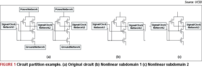
The proposed approach reads the circuit description in SPICE format and partitions the circuit at linear and nonlinear boundaries at gate level. The circuit is partitioned into a linear subdomain and multiple nonlinear subdomains. First, we partition the circuit into different nonlinear partitions (i.e., subdomains) based on circuit nonlinearity and connectivity. Figure 1(a) shows an example of two NAND gates surrounded by coupled power, ground and signal networks. Figure 1(b) and 1(c) show two different nonlinear subdomains. The nonlinear subdomains include nonlinear functional blocks as well as input/output signal networks connected to these functional blocks. Power and ground networks are not included because we need to make the nonlinear subdomains small enough to be solved efficiently by a direct solver. Partitions that break feedback loops are avoided. Since these feedback loops usually are not very large, it is feasible to keep them in a single nonlinear subdomain.
Once the circuit is partitioned into different nonlinear subdomains ?1, …, ?k, we add the whole circuit as a linear subdomain ?0. Unsymmetry in the system matrix of ?0 caused by nonlinear components in the circuit are removed as described in 2C in order to improve the matrix properties of ?0. This allows us to use parallel iterative matrix solvers to solve the linear subdomain efficiently. We use the parallel graph partition tool ParMETIS [9] to further partition the linear subdomain ?0 to achieve parallel load balance and make the proposed approach scale with the number of processors.
B. Gate decoupling and topological order simulation
Because of nonlinear elements in the circuit, the system matrix for linear subdomain ?0 is not symmetrical and hence it is unsuitable for fast parallel linear solvers. The main asymmetry in the matrix comes from the gate-source and gate-drain coupling in device models. We move this coupling from the system matrix of the linear subdomain to the right hand side of the linear system. For example, the following sub-matrix demonstrates gate-drain coupling in the BSIM3 model:
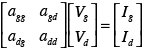
We move the off diagonal terms in the matrix to the right hand side:
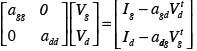
where Vtd and Vtg are solutions at previous iteration.
This process simplifies the linear subdomain and improves the matrix properties of the system matrix. With this simplification, we could use parallel solvers like GMRES to solve the matrix efficiently. The linear subdomain ?0, which is the entire circuit with simplification, is then partitioned by ParMETIS and solved in parallel using GMRES with BoomerAMG as a preconditioner. Nonlinear subdomains are evenly distributed into different processors and solved by the direct solver KLU [13].
To increase the convergence rate, we generate a topological order from primary inputs and flip-flops in the circuit and solve nonlinear subdomains according to this order. Feedback loops are reduced into a single node when the topological order is generated. Convergence is achieved by using parallel domain decomposition techniques, which will now be introduced in 2C.
C. Parallel domain decomposition techniques for circuit simulation
Domain decomposition methods refer to a collection of divide-and-conquer techniques that have been primarily developed for solving partial differential equations [10], [11]. The partition method introduced in 2A generates overlapping subdomains. For example, as shown in Figure 1, nonlinear subdomains 1 and 2 overlap as they share the same signal/clock network 2.
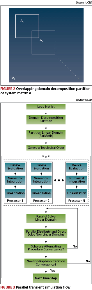
Partitioning the circuit into a linear subdomain ?0 and K overlapping nonlinear subdomains ?1, … , ?k is equivalent to partitioning the system matrix A of the circuit into a matrix A0 and K overlapping sub-matrices A1, …, AK as shown in Figure 2, where Ai is the matrix representing subdomain ?i.
Schwarz Alternating Procedure [11] is used to iteratively solve the linear system Ax=b. The algorithm is described below. The proposed method first solves the linear subdomain ?0. The linear subdomain is partitioned by ParMETIS and solved in parallel using GMRES with BoomerAMG as a preconditioner. Next, all nonlinear subdomains ?1, …,?K are distributed into different processors according to their topological order and solved by the direct solver KLU. Residue values at a subdomain boundary are updated as soon as the solution for a given subdomain is available. The Schwarz Alternating Procedure continues until convergence is reached.
Schwarz Alternating Procedure
- Input: Matrices A, A0, A1, …, AK, right hand side b.
- Output: Solution x
- Choose initial guess x
- Calculate residue r = b?A x
- repeat
- for i = 0 to k do
- Solve Ai?i = ri
- Update solution x. xi = xi+?i
- Update residue values on boundary
- end for
- until Convergence
- Output x
D. Parallel device loading
Device model evaluation, an essential part of a circuit simulator, could easily consume more than 30% of the total runtime in a serial simulation. For parallel circuit simulation, the device model evaluation part becomes more sensitive as it will introduce significant communication overhead if it is not done in parallel and optimally. The proposed method performs the device loading, numerical integration and linearization steps in parallel. Once the circuit is partitioned, each processor calculates the device model, numerical integration and linearization for its own partition. This approach reduces the device model evaluation runtime and reduces the communication overhead needed for the stamping of Jacobian matrix entries among the processors.
E. Parallel transient simulation flow
The overall parallel transient simulation flow is presented in Figure 3. The device loading, numerical integration and linearization steps are the same as Berkeley SPICE except that they are done in parallel. As shown, the linear subdomain is partitioned into N partitions by ParMETIS, where N is the total number of available processors. Each processor loads its own part of the circuit. After the parallel device loading, numerical integration and Newton-Raphson linearization, the linear subdomain is solved in parallel. Nonlinear subdomains are then evenly distributed into available processors according to their topological order and solved by a direct solver.
3. Experimental results
The proposed approach was implemented in ANSI C. Parallel algorithms are implemented with MPICH1. We adopted the same dynamic step size control, numerical integration and nonlinear iteration methods as are used in Berkeley SPICE3. The GMRES solver and BoomerAMG preconditioner in the PETSc [12] package were used as iterative solvers, and KLU [13] was used as a direct solver. Five industrial designs were tested on the FWGrid [14] infrastructure with up to 64 processors. Table 1 lists the transient simulation runtime, where DD refers to the proposed method.
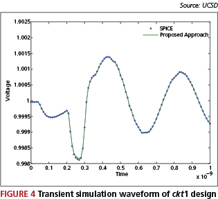
Test cases ckt1 and ckt2 are two linear circuit dominant test cases. Figure 4 shows the waveform of one node of the ckt1 circuit. The waveform shows that our result matches the SPICE result. Test cases ckt3, ckt4 and ckt5 are cell designs with power and ground networks. We can see from Table 1 that the proposed method is orders of magnitude faster than SPICE.
The results also show that the proposed method scales very well as we increase the number of available processors. However, the performance increase from 32 to 64 processors is not as great as the increase from 16 to 32 processors. This is due to cross-rack communication overhead on the FWGrid infrastructure. With 64 processors, we need to use at least two racks as each rack on a FWGrid has only 32 processors. The ParMETIS partition of the linear subdomain is very important for parallel scalability, as we have noticed that without ParMETIS it is very hard to achieve performance gains when more than 16 processors are used.
| Case | #Nodes | #Tx | #R | #C | #L | SPICE | DD (1 Proc.) |
DD (4 Proc.) |
DD (16 Proc.) |
DD (32 Proc.) |
DD (64 Proc.) |
| ckt1 | 620K | 770 | 550K | 370K | 270K | 4,257s | 661s | 245s | 106s | 58s | 49s |
| ckt2 | 2.9M | 3K | 1.9M | 1.2M | 810K | N/A | 18,065s | 6,429s | 2,545s | 1,493s | 1,179s |
| ckt3 | 290K | 80K | 405K | 210K | 0 | 20.5h | 4,761s | 1,729s | 703s | 439s | 337s |
| ckt4 | 430K | 145K | 360K | 180K | 50K | 49.4h | 7,297s | 2,731s | 1,182s | 782s | 596s |
| ckt5 | 1M | 6.5K | 2.2M | 1M | 5K | N/A | 5,714s | 2,083s | 855s | 443s | 318s |
| Transient simulation runtime | |||||||||||
4. Conclusions and future research
A fully parallel circuit simulation tool for transistor-level simulation of large-scale deep-submicron VLSI circuits has been presented. An orders-of-magnitude speedup over Berkeley SPICE3 is observed for sets of large-scale real design circuits. Experimental results show an accurate waveform match with SPICE3.
For future work, we would like to extend this method to supercomputers with hundreds of processors. Parallel load balancing and machine scheduling techniques will be developed to ensure our tool scales with growing numbers of processor and for circuit sizes with hundreds of millions of elements.
Acknowledgment
The authors would like to acknowledge the support of NSF CCF-0811794 and the California MICRO Program.
References
- [1] L. Nagal, ”Spice2: A Computer Program to Simulate Semiconductor Circuits,” Tech. Rep. ERL M520, Electronics Research Laboratory Report, UC Berkeley, 1975
- [2] K. Sun, Q. Zhou, K. Mohanram and D. C. Sorensen ”Parallel domain decomposition for simulation of large-scale power grids”, in Proc. ICCAD, 2007, pp. 54-59
- [3] W. Dong, P. Li and X. Ye ”Wavepipe: Parallel Transient Simulation of Analog and Digital Circuits on Multi-core Shared-memory Machines”, in Proc. DAC, 2008, pp. 238-243.
- [4] X. Ye, W. Dong, P. Li and S. Nassif ”MAPS: Multi-Algorithm Parallel Circuit Simulation”, in Proc. ICCAD, 2008, pp. 73-78.
- [5] H. Peng and C.-K. Cheng, ”Parallel Transistor Level Circuit Simulation using Domain Decomposition Methods”, in Proc. ASPDAC, 2009, pp. 397-402.
- [6] N. Frohlich, B. M. Riess, U. A. Wever, and Q. Zheng ”A New Approach for Parallel Simulation of VLSI Circuits on a Transistor Level”, IEEE Transactions on Computer-Aided Design of Integrated Circuits and Systems, vol. 45. No.6, June 1998
- [7] S. Hutchinson, E. Keiter, R. J. Hoekstra, H. A. Watts, A. J. Waters, R. L. Schells and S. D. Wix ”The Xyce Parallel Electronic Simulator – An Overview”, IEEE International Symposium on Circuits and Systems, Sydney (AU), May 2000
- [8] A. Ruehli and T. A. Johnson ”Circuit Analysis Computing by Waveform Relaxation”, in Encyclopedia of Electrical and Electronics Engineering, vol. 3, Wiley, 1999.
- [9] G. Karypis, K. Schloegel and V. Kumar, ParMETIS – Parallel Graph Partitioning and Sparse Matrix Ordering, University of Minnesota, http://glaros.dtc.umn.edu/gkhome/metis/parmetis/overview, 2003
- [10] B. Smith, Domain Decomposition: Parallel Multilevel Methods for Elliptic Partial Differential Equations, Cambridge University Press, 2004.
- [11] Y. Saad, Iterative Methods for Sparse Linear Systems, SIAM, 2003.
- [12] S. Balay, K. Buschelman, V. Eijkhout, W. D. Gropp, D. Kaushik, M. G. Knepley, L. Curfman McInnes, B. F. Smith and H. Zhang, PETSc Users Manual, ANL-95/11, Argonne National Laboratory.
- [13] T. A. Davis, Direct Methods for Sparse Linear Systems, SIAM, Philadelphia, Sept. 2006. Part of the SIAM Book Series on the Fundamentals of Algorithms.
- [14] FWgrid Home Page: http://fwgrid.ucsd.edu/
Department of Computer Science and Engineering
University of California, San Diego
La Jolla
CA 92093-0404
USA