Catch the next wave in DFT automation
 Jay Jahangiri is a Product Manager specializing in DFT for Mentor, a Siemens Business.
 How many hopeful design starts end in a missed market opportunity because of inefficient, or downright broken, design-for-test (DFT) flows? For increasingly large and complex SoCs, DFT can take too long and introduce risk in the critical path to tape-out. There is a production-proven methodology to shorten DFT implementation time and eliminate risks to the design schedule. It takes a little upfront planning, but the ROI is unquestionable. The solution is an RTL-based hierarchical DFT flow with end-to-end smart automation.
For designs that use flat or partially hierarchical flows, assembling a new design flow and methodology presents problems of its own. Retrofitting an existing, flat DFT flow with increasingly common hierarchical DFT steps requires a lot of manual intervention. This in turn often introduces errors and inefficiencies. Tessent Connect addresses these challenges by simplifying the adoption and implementation of a hierarchical DFT flow. The goal is to establish end-to-end DFT automation that better connects the people, processes, and tools involved. The flow should be reliable, sustainable, flexible, and highly customizable.
Divide-and-conquer with hierarchical DFT
Many SoCs today are too large for a traditional flat or partition-based approach to DFT with manual steps. Breaking designs into smaller pieces makes physical implementation more manageable for designers as well as for EDA tools. This approach also lets you take advantage of cores that have many identical instantiations, as seen in many AI designs. All the design effort goes into one instance, which is then instantiated as many times as required. DFT benefits from a similar divide-and-conquer approach that is consistent with the rest of the design flow and addresses the same problems with large designs.
Most projects today use some form of hierarchical design in which cores are concurrently designed by different teams or individuals, then assembled and finished at the chip level. Hierarchical DFT uses the existing hierarchy of an SoC to insert all DFT and generate test patterns at the core level. The lowest level of hierarchy is the ‘core,’ which can be a single core or a group of cores. Some designs group many smaller cores together for ATPG in order to share scan channels and minimize routing. Cores are isolated with core-level clocking and wrapper chains. All DFT insertion, verification, and pattern generation are performed at the core level. Patterns are retargeted to the chip level, where cores are represented by graybox models.
Hierarchical DFT requires a few key technologies such as core wrapping for core isolation, graybox model generation to reduce machine memory consumption, and pattern retargeting to re-use core level generated patterns. Figure 1 illustrates chip-level DFT in a hierarchical DFT methodology.
Figure 1. Chip-level ATPG in a hierarchical DFT methodology (Mentor)
The move to hierarchical DFT has led to dramatic improvements in all aspects of DFT. Some of the largest chip makers, including Amazon (D. Trock, 2016) and Samsung (B. Shin, 2019), have published their results demonstrating the benefits of hierarchical DFT.
Another trend in DFT is to migrate the work upstream into the RTL. An RTL-based DFT flow needs to be merged with front-end design flow so tasks can be managed in a repeatable, reliable manner that facilitates the downstream integration.
You can translate legacy, flat DFT flows to hierarchical flows, but it takes a lot of manual work. Typically, the designer has to describe every step the DFT tools should take and repeatedly input the same information to each step. This approach adds significant time to the flow, complicates debug and can introduce errors.
Elements of end-to-end DFT automation
Hierarchical DFT benefits from having a fully automated DFT solution—including a set of DFT tools that work on a common platform—that can take general user directives across all parameters (test time, area consumption, power consumption, etc.), to make smart decisions that balance test costs, time, and coverage.
As DFT necessarily migrates further upstream into the RTL, it becomes increasingly important to merge it into the front-end design flow, manage tasks in a repeatable flow, and maintain design awareness to facilitate downstream integration.
The elements of optimal end-to-end automation for DFT flows can be described in three main categories (also in Figure 2):
- Intent-driven automation
- Universal test infrastructure
- Future-proof customization
Figure 2. Mentor’s Tessent Connect is end-to-end automation for hierarchical DFT flows (Mentor)
These capabilities enable efficient concurrent design with easy hand-off between teams that reduce DFT time and increases predictability. These are the capabilities to look for when planning DFT for your next project. This end-to-end DFT automation reduces the complexity of many DFT steps and accelerates time-to-market. Users can work at a higher level of abstraction. The challenge of inserting DFT, creating patterns, and integrating the DFT functions at the top level are all managed in a unified, plug-and-play environment. Without such an integrated platform, companies struggle to manage DFT functions such as BIST and ATPG and face the need to take many steps to integrate core-level DFT and patterns at the top level.
Intent-driven automation
Intent-driven automation empowers designers to describe high-level test goals to the DFT tool early in the flow rather than writing detailed, step-by-step scripts at every DFT stage. For example, say a designer needs to setup ATPG for different scan modes. Typically, he or she would have to write multiple scripts, keep track of the scripts and procedure files, and then load the correct setup files for each test mode. But with intent-driven automation, all the scan configurations (internal, external, bypass mode, etc.) are inserted at once and stored in a common database. Then, during ATPG, the tool only needs to know which scan mode to import and it can then take care of the details.
Having all DFT tools on a common database ends up being very important from a flow usability perspective. With this new automation, all the data and generated files are organized hierarchically in the database and called on throughout the flow as needed. For example, when the designer generates the database for a particular project in which he or she has inserted memory BIST, EDT, IJTAG, etc., the different components, instruments, patterns, and information needed for subsequent steps are stored in sub-directories with meaningful names and structure. A database setup is shown in Figure 3.
Figure 3. Common database structure (Mentor)
The high-level DFT specification that captures the designer’s intent starts with a network to allow access and control of IJTAG-compliant on-chip resources. The specification guides memory BIST insertion (type, number, grouping, location) and scan insertion (number and type of EDT controllers, chains per controller, locations). It also manages clocking control, power, and custom DFT signals and verifies that all the setups have no errors. It even generates the SDC files needed for physical design signoff.
Universal test infrastructure
End-to-end DFT automation relies on IEEE 1687, a.k.a IJTAG, infrastructure for plug-n-play automation across all test instruments. The ability to universally use any vendor’s IJTAG-compliant IP significantly eases core and IP integration and reuse. It also allows the core-level test patterns to be retargeted to the higher levels and to broadcast the patterns to identical cores. Figure 4 illustrates an IJTAG network with sub-networks for scan test instruments. Advanced DFT automation can insert the IJTAG network, recognize and extract exiting IJTAG networks, incrementally create ICL and PDL network description files, and perform hierarchical PDL retargeting. It automatically creates the optimal IJTAG network configuration with efficient implementation of IJTAG instruments and test-data registers (TDRs) used for specific writes/reads.
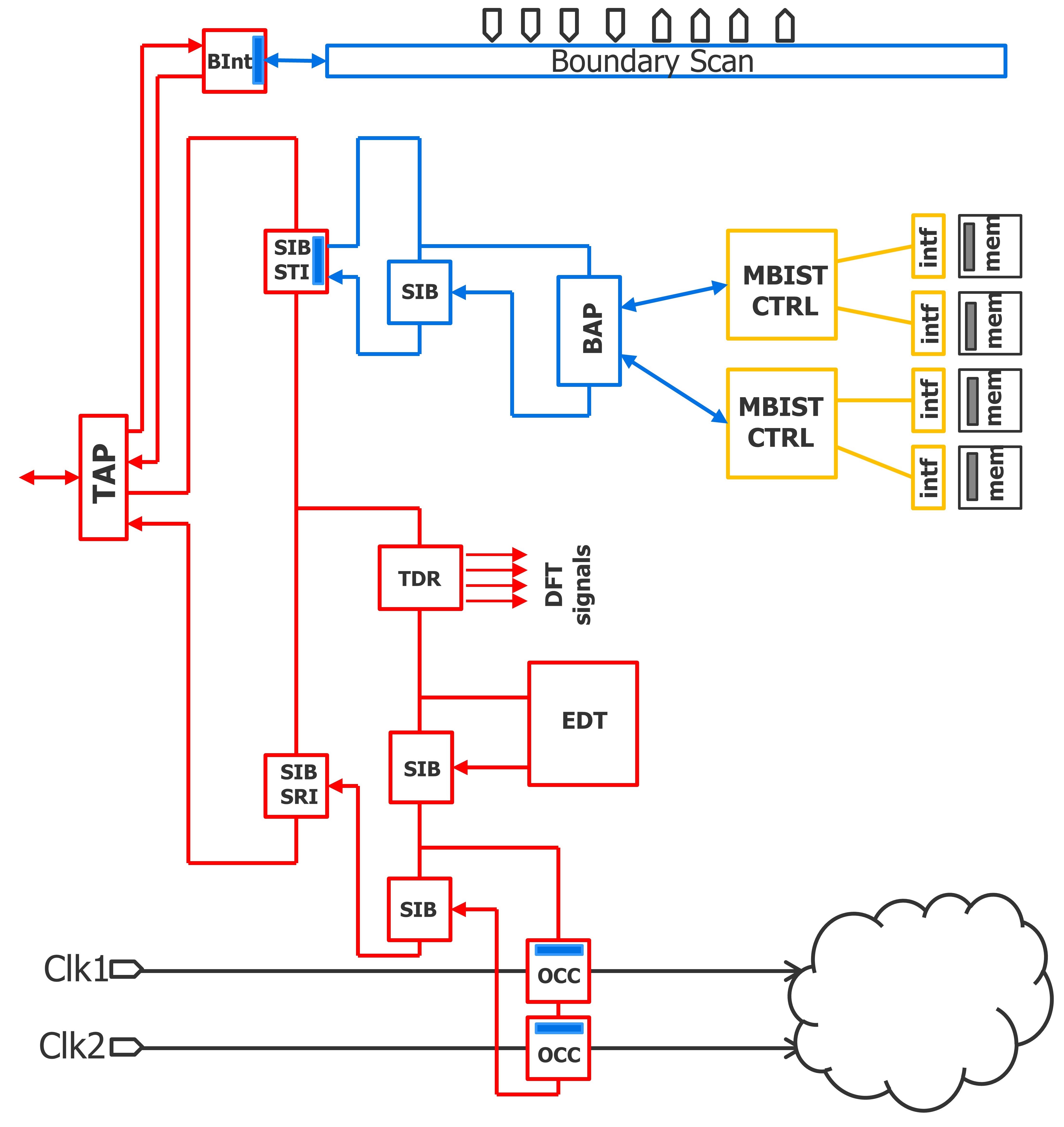
Figure 4. Example IJTAG network implementation (Mentor)
A universal test infrastructure also simplifies the initialization procedures for a TAP controller. The cycle-by-cycle procedure creation process can be very time-consuming and error-prone. Now, it can be accomplished at a higher level of abstraction that enables automatic procedure creation through simple-to-use commands and built-in procedures.
Future-proof customization
Adopting a complete hierarchical flow from scratch might not be practical, so design teams need to be able to seamlessly integrate existing custom design steps and requirements into this more advanced automation methodology. The flow can be customized to perfectly suit individual users, groups, or company-wide requirements.
This flexibility in adoption is achieved by having multiple entry/exit points, and it welcomes custom and third-party tools. Using powerful introspection and Tcl scripting capabilities can blend standard tool features and commands with user-defined commands and scripts.
Examples of future-proof customizations include:
- The creation and automatic execution of DRCs to check the status of enable pins on clock-gaters, check that memories are in bypass mode or enabled, check the slew rate of I/O pads, and more besides;
- The introspection of design and tool data models;
- The addition of new user-defined attributes to track and fully introspect custom settings; and
- The ability to change tool and user-defined attributes on any object type.
Adopting end-to-end DFT automation is made easier with the help of a trusted, market-leading tool supplier who can assess your current DFT goals and provide complete reference flows, documentation, and test cases along with the tools. As more of Tessent Connect’s end-to-end DFT automation is deployed, you can see progressively further reductions in DFT implementation time and cost and a more efficient, predictable, and sustainable DFT flow. Broadcom’s ASIC division used Tessent Connect and presented their experience at the International Test Conference last year. You can watch the 13 min presentation here.