Firmware verification using SystemVerilog OVM
Your current verification strategy, no matter how robust, may not always satisfy the latest demands placed upon it given the rate of change in semiconductor design. To stay at the forefront of innovation, you must be willing and able to take advantage of the potential in emerging and evolving technologies.
It is not simply that these may be better capable of dealing with the challenges of verifying state-of-the-art hardware. When you help drive the development of new technologies, you not only secure immediate benefit for today’s projects, but by helping to shape them, you also receive long-term benefits by making sure they improve over time in a manner that best suits your requirements. This kind of influence is more difficult to get if you commit to a proprietary flow or language.
The Open Verification Methodology (OVM) offers both an open, de facto standard and the advantage of being a recent methodology developed specifically to address current verification challenges. OVM enabled the creation of a complex, well-structured, reusable testbench infrastructure and provided highly useful technologies such as constrained-random stimulus generation and functional coverage.
The value of new technologies and methodologies holds especially true when the verification methodology itself is innovative. In this case, a pilot project undertaken by Infineon Technologies Singapore, the team used SystemVerilog and the OVM in a fresh and creative way for the verification of firmware. We expect that this application of OVM will become more commonplace as firmware is now integral to systems and no longer a late-stage add on.
Choosing the best methodology and the best language
The project team’s search for a new language and methodology was guided by several criteria. Among other things, the team wanted an open standard; advanced verification features; highly reusable components in an easy-to-use package; and internal access to the VHDL design from the simulator and the testbench.
Standard language, open-source methodology
The main motivation for moving to a new language was to adopt a proven, standards-based environment. SystemVerilog fit this description and another benefit was that it was supported by an open-source methodology, OVM. There are many advantages to a standard, open-source approach, but the main ones in this case were maximized interoperability and EDA cost control.
Cost-effective and vendor-independent solutions are preferable as long as verification functionality is not compromised. Non-proprietary languages allow a more budget-conscious use of EDA budgets because users do not have to pay for proprietary licenses and can reuse IP and verification components written in different languages.
Standard languages and open source code are proven and robust due to widespread use. For the same reason, they evolve more rapidly thanks to a combined effort that is directed through a large community of users.
Automated test and coverage
Another basic requirement was access to a high-level verification language (HVL) that supports constrained-random generation and native coverage collection capabilities. In firmware verification, many configurations and scenarios have to be tested. Therefore, constrained-random tests are preferable to directed tests because they reduce the amount of test code you need to write to adequately cover all of a design’s functionality. Infineon uses functional coverage and code coverage as the main metrics to judge the quality of verification.
Well-known and proven approaches to constrained-random stimulus generation and to analyzing simulation results by employing functional coverage are among the main features of the OVM.
Reuse
Increasing design complexity and shortened time-to-market make the reuse of verification infrastructures critical. This means that components must be modular and highly configurable, so that the effort required to adapt them to different devices-under-test (DUTs) is minimal.
SystemVerilog provides object-oriented programming (OOP) constructs. These in turn enable the development of well-structured environments that facilitate reuse, and the language’s unique extensions to functionality support a modular approach in an optimal way. The reuse of such components and elements is easy and independent of the compilation order, and this significantly reduces the risk of compilation errors. The OVM and SystemVerilog’s OOP mechanisms provide a well-structured environment that eliminates many of the risks of reusing components.
Because OOP languages lend themselves well to the development of well-structured code, and because of the lack of compilation problems with SystemVerilog and OVM, you can easily share code, models, and components across big design teams. In the SystemVerilog and OVM worlds, these are correct-by-definition due to the object-oriented foundation for SystemVerilog and the modular nature of OVM.
The team on this project also found that a well-structured approach to the use of transaction-level modeling (TLM) makes reuse very straightforward. Indeed, TLM is one of the biggest benefits of OVM. TLM was originally developed in the SystemC world and was subsequently adapted for use in SystemVerilog. In e, the language Infineon had been using, there are accommodations to use TLM, but e does not have the comprehensive libraries that are necessary for full support.
Ease of use
Because it is an extension of the Verilog Hardware Design Language (VHDL), SystemVerilog lowers the barrier for entry to OVM as many of the constructs are familiar to Verilog users. The OVM kit provides proven code examples from which useful pieces can be extracted as well as a base class library for developing the elements of a testbench. Due to their modular nature, these can later be augmented or rearranged to make new testbenches.
The adoption of a new methodology and language typically requires more work in the early stages of a project. OOP sometimes needs more lines of code compared to an aspect-oriented programming (AOP) methodology. Yet those extra lines enabled us to adopt the more structured approach we sought, so the benefits (no compile problems, reuse, and concurrent verification) far outweighed the upfront effort. Indeed, the compile issues inherent in an AOP strategy required more work to resolve than that required to write the extra OOP code. In addition, with OVM a great deal of the code is provided for you.
Controllability and observability
Verifying firmware requires a lot of internal access to the VHDL design from the simulator and the testbench. Because the Verilog community drove the development of SystemVerilog, VHDL is not transparent to it. It should be noted that this limitation only occurs with VHDL, not Verilog.
SystemVerilog provides the bind construct, which provides access to arbitrary nodes in a VHDL design. However, this construct is intended for observability and not necessarily controllability. This limitation of the language is addressed later in this paper.
Firmware verification methodology
When building new testbenches with OVM, the goal was to use the same firmware verification methodology the team had used in e. The team chose to start from scratch rather than migrate portions of the e testbench to SystemVerilog because it did not have a testbench compliant with the e Reuse Methodology (eRM) and also because there are fundamental differences between the two languages.
This decision also provided an opportunity to make all of the OVM verification components (OVCs) more structured. Whereas the previous e environment was not well structured, OVM infrastructures are. This is a big advantage when it comes to long-term maintenance and reuse.
Building an OVM testbench from scratch certainly takes some effort. For example, the team needed to understand the OVM technology, its guidelines, and make its firmware verification methodology fit into this. Then, the methodology had to be built.
As the project progressed the team became convinced that the OVM methodology and technology were quite impressive and worth the initial ramp up. It is a structured methodology and truly beneficial, especially with reuse.
Design description
The DUT was mainly coded in VHDL with some IP blocks coded in Verilog. It was instantiated by a VHDL top-level testbench used for SoC verification (Figure 1). The SystemVerilog/OVM top-level was instantiated under this VHDL top-level.
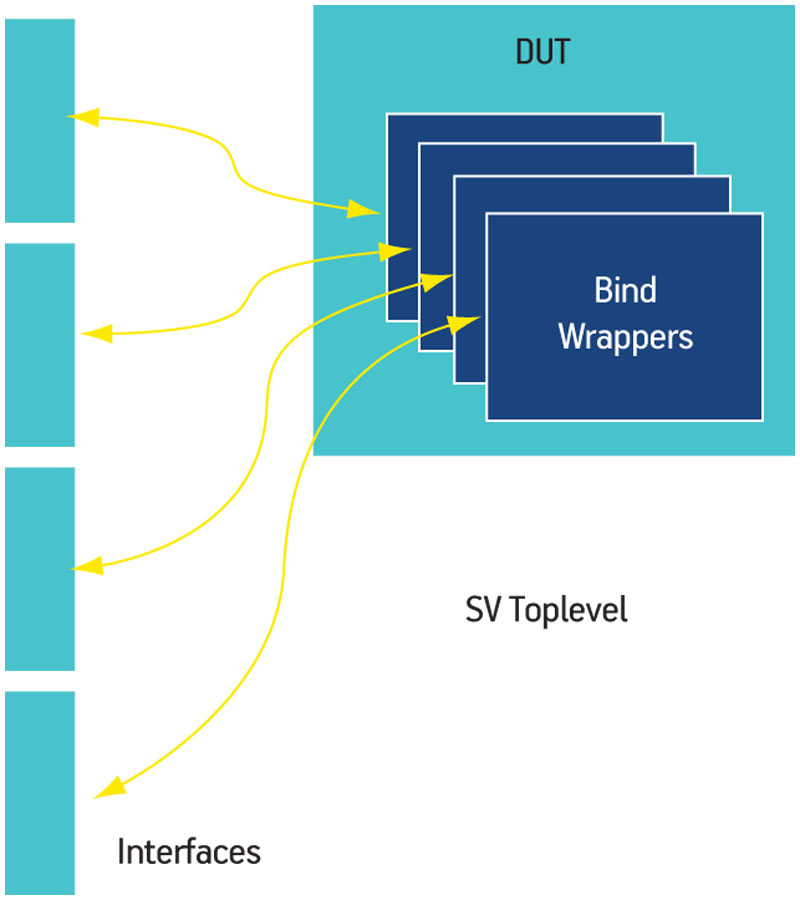
Figure 1
VHDL top-level testbench
OVM test environment
Layer 1
The first layer of the OVM test environment (Figure 2) consisted of an interface layer for observing and driving signals into the DUT. Firmware verification differs from a conventional bus functional model (BFM) because you are mostly interested in whitebox testing. Instead of a BFM model, this project used a signal map. A signal map is a collection of internal signals that are of interest to our verification plan, and implements methods for observing and driving them. Here, the design team used the bind construct to observe the internal VHDL signals and the Mentor Graphics Questa SignalSpy technology to drive them.
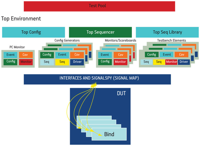
Figure 2
The OVM test environment
Layer 2
The second layer consisted of the OVCs. The project used a proprietary OVC template and guidelines to develop the components. The OVCs are configurable using parameters and/or macros. TLM analysis ports and TLM analysis FIFOs are used for the OVC interconnections. TLM analysis ports provide simple and powerful transaction-based communication because of their ease of implementation, support for multiple connections, and execution in the delta cycle.
In general, our firmware verification testbench has four types of OVC: program counter (PC) monitor, config generator, monitor/scoreboard, and testbench element.
The PC monitor is the main OVC. It is responsible for monitoring the PC, decoding the PC, and triggering an ovm_event when the PC matches a label in the firmware code. In addition, it will collect PC data for code and branch coverage. All other OVCs in the testbench need an object handle to this PC monitor class.
The config generator OVC creates the constrained-random stimulus and feeds it into the DUT that will influence the behavior of the firmware execution.
The chief function of the monitor/scoreboard OVC is to observe and compare signals in the DUT against the stimulus generated by the generator OVC in response to events triggered by the PC monitor (Figure 3). The monitor OVC contains the required functional coverage points. Only if all the conditions and checks for a coverage point are met will it be sampled by the covergroup.
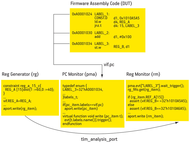
Figure 3
An example of event-based (program counter) assertions in firmware verification
The testbench element OVC is usually a communication component that interacts with the DUT on the port interfaces. Examples include the JTAG module and bootstrap loaders. This OVC performs a specific task using the actual protocol of the communication component.
Layer 3
The third layer was the top-level OVM environment and configuration layer. It instantiates all the OVCs and creates the TLM connections. The top config block configures the sub-configs in each of the OVCs for a specific DUT. A virtual top sequencer controls the config generators, the OVC’s sequencer, and the testbench element OVC’s sequencer. The top sequencer library contains complex sequences involving two or more of the OVCs, such as pipelined sequences whereby the output of one generator OVC is needed by another generator OVC.
Layer 4
The fourth layer contained the OVM test pool. Each test specifies a particular scenario to run in the testbench. The test pool configures the environment by using factory override methods.
Firmware verification results
The focus for verification in this project was the firmware, made up of assembly ROM code in the microcontroller. The firmware code contains the very first instructions that will be executed by the microcontroller upon boot up. Proper execution upon power-on must be ensured to put the device into a functional state. Any bug in the firmware that causes the startup to fail will render the MCU unusable. Since the firmware is hard-coded, a bug here would make a respin necessary, driving up the cost of development significantly.
We found 12 firmware bugs and five hardware bugs using the OVM for firmware verification. Common firmware bugs were the result of the implementation not meeting specification (these were detected by assertions) or implementations that did not cover all possible scenarios in the firmware (detected by random stimulus generation and coverage). Firmware verification quite often also detects hardware bugs (through assertions) caused by registers that are not writable or readable because either their protections are not set correctly in the RTL or their top-level connections are incorrect.
Experiences and lessons learned
We were able to pursue the goal of constructive, meaningful innovation in the sense that this was a successful pilot project using OVM and SystemVerilog for firmware verification. The success of the pilot convinced us that we could reuse most of our firmware test environment for future projects, especially the OVM portion.
OVM provides comprehensive guidelines for building a complete verification environment. It extends tested and proven coverage-driven, constrained-random verification with practical resources in its class libraries. It facilitates reuse and configuration by using the OVM factory method, and TLM provides a standard and simple data transaction between verification components. These OVM features enabled a reusable and modular approach to design verification.
The OVM methodology and technology were quite impressive and worth the initial ramp up. OOP does sometimes require more lines of code, compared to AOP, but the extra work allowed us to reach our primary goal of a more structured approach. On subsequent projects, the amount of effort associated with the OVM and the number of workarounds required for it should also decline.
The main challenges were encountered in the first layer of the verification architecture: implementing the bind mechanism to connect to internal nodes of the VHDL design and feeding these connections back into the OVM testbench. The objective was to provide a complete language-based interface for the observation and forcing of internal nodes. So far, this objective has been reached only for observation.
The team resolved the control issue by using SignalSpy, a Questa utility that provides access to internal design nodes to drive signals. However, it is not a language-based approach. The employment of the force functionality in SignalSpy conformed to OVM guidelines without generating serious issues.
To avoid changing existing force files to accommodate testbench development (required by the standard Infineon OVM testbench architecture), the top-level testbench had to be in VHDL. OVM does not require a SystemVerilog top-level module. Therefore, this could be easily managed. The implementation of testbench elements for the design (JTAG, etc.) involved separate tasks and was performed following the OVM guidelines.
Future improvements
The main challenge of this project was the implementation of the signal map layer. The use of the SystemVerilog bind construct was not suitable for whitebox verification because it cannot be reused if the design changes. Furthermore, SystemVerilog bind is limited when it comes to VHDL designs.
For future improvements, it would be a good idea to explore the possibility of replacing the signal map with an OVM register package to access the internal registers of the DUT. A register package will be provided in the near future by the OVM organization and, once available, this should solve the controllability issue.
SystemVerilog should be extended to improve the driving of internal signals in VHDL designs. VHDL users will emphasize this requirement for obvious reasons. This is not an issue for Verilog portions of a design or IP.
Based on this pilot project, we recommend the following enhancements to SystemVerilog:
- Deliver improved documentation for the SystemVerilog bind construct to make its employment easier and more powerful.
- Provide a language-based approach for access to internal nodes in VHDL designs for observation and forcing.
Infineon Technologies Asia Pacific
8 Kallang Sector
349282 Singapore
Mentor Graphics
Corporate Office
8005 SW Boeckman Rd
Wilsonville
OR 97070
USA
T: +1 800 547 3000
W: www.mentor.com
Hi,
This is really a good article. I came across similar situation and implemented few assertions to check these booting issues (mean firmware), but at that point of time I am not sure if that is a correct procedure. But after going through your article, it looks like I have chosen correct approach.
Thanks
-Thrilok