Characterizing PLL jitter from power supply fluctuations using mixed-signal simulations
Characterizing PLL jitter is important yet challenging. Usually done through transistor-level transient analysis, a slow simulation speed has been the major bottleneck preventing jitter from being characterized in a timely manner. This paper presents an approach for fast jitter characterization using mixed-signal simulation (a combination of transistor-level blocks and calibrated behavioral models). Among various PLL jitter mechanisms, jitter from CMOS gate switching threshold variation due to power supply fluctuations has been chosen as the focus. Analog-to-digital converters carrying dynamic power supply dependency are used together with behavioral models written in Verilog-AMS to approximately model and characterize the targeted type of jitter.
Introduction
Phase-locked loops (PLLs) are widely used on designs such as frequency synthesizers and clock recovery circuits. Undesired timing variation from noise is not only a crucial factor for performance degradation, but also a cause of functional failure when severe. It must therefore be characterized properly. Phase noise and jitter are two standard metrics for timing variation characterization. The former can be extracted from frequency-domain analysis using popular RF simulators; the latter is usually extracted from time-domain transient analysis more common for digital applications.
One major bottleneck in jitter characterization is the slow speed of transient simulation that is performed at the transistor-level. In recent years, mixed-signal simulation combined with system representations of behavioral models and transistor-level blocks has become an increasingly popular technique in tackling this issue. Here, mixed-signal simulation, behavioral models and analog-to-digital converters carrying dynamic power supply dependency are applied to a PLL design to enable fast-yet-accurate jitter characterization.
As analyzed by Kundert [1], there are many different types of jitter in PLLs. This paper focuses on jitter caused by the CMOS gate switching threshold variation due to power supply fluctuation.
Noise characterization methods
Phase noise and jitter are two standard metrics for PLL noise characterization. Although the underlying physical effects to be measured are the same, the concepts are defined in different domains and suit different application areas.
In RF design, it is not uncommon for the design specification to set limits on both metrics, obliging designers to measure and meet both. For RF design, frequency-domain analysis using RF simulators is usually the first choice. Jitter is then derived from the measured phase noise using conversion equations [2].
However, such conversions are usually based on approximations that might not be applicable to every scenario. So, a transient simulation would still be needed at the final design stage to ensure the jitter specification is met as well.
Due to the co-existence of lower-frequency data and a high-frequency carrier, transient simulation for RF design generally has a long stop-time and runs very slowly. For digital applications, transient analysis is usually preferred and jitter is more often used as the metric. Traditionally, simulation is performed at the pure transistor-level in SPICE-like simulators.
Due to the needs for a long simulation time in the order of milliseconds for accurate jitter characterization, and for multiple runs for individual block characterization and iterative design optimization, slow transient simulation at the transistor-level has become a serious bottleneck in jitter characterization.
There are different approaches to speed up transient simulation. Fast-SPICE tools greatly boost the performance. However, there is an inevitable compromise in accuracy, and attempts to improve it can heavily degrade performance.
Mixed-signal simulations using behavioral models speed up transient simulation as well. Unlike transistor-level simulation, a better balance between accuracy and speed can be obtained as the behavioral models are mathematical descriptions of physical behavior at abstraction levels that are higher than device models in SPICE. Mixed-signal simulations have been proved to be fast yet accurate enough, especially for mixed-signal systems such as PLLs where analog behaviors are the major cause of slow-down.
Jitters in PLL
There are various jitter sources in PLLs. As categorized by Kundert [1], PLL blocks such as the PFD, CP and FD are driven blocks exhibiting synchronous jitter; while blocks such as the VCO are autonomous blocks exhibiting accumulating jitter. Different types of jitter not only imply different underlying physical mechanisms, but also lead to different jitter definition and characterization methods.
The specific type of jitter to be studied in this paper is the synchronous jitter in PLL-driven blocks caused by the variation in CMOS gate switching threshold due to power supply fluctuation.
Supply fluctuations can be caused by intrinsic noise in an impure power supply, by substrate noise, or more often, by coupling between several functional blocks on the same chip. The last of these must be characterized then suppressed, especially for mixed-signal system-on-chips (SoCs) where the switching from digital parts has a significant effect on the sensitive analog parts. Compared to internal device noise, supply noise usually has a non-white power spectral density, demonstrating peaks at various frequencies, and more importantly, has a strong dependency on the location (circuit nodes) where the noise is introduced [3].
According to Rabaey et al [4] and Kang & Leblebigi [5], the gate-switching threshold, Vth , of a CMOS inverter varies with power supply voltage Vdd , following the equation below:
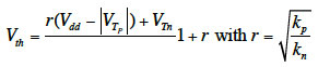
where r ≅ 1when the inverter is symmetric (kp=kn), indicating a strong dependency of Vth on Vdd . Note that short-channel effects are neglected here as an approximation.
Many other logic blocks function based on a similar principle of gate switching threshold detection, including the PLL building blocks shown in Figure 1. Such variations in threshold detection along with power supply noise lead to the targeted type of clock jitter in the PLL output.
Jitter characterization with mixed-signal simulation
PLL jitter characterization usually requires measurement of the jitter contribution from individual blocks within the frame of the whole PLL. This helps us to understand the noise contribution of each block for design tuning, but requires multiple simulations. Considering both the long stop-time of accurate jitter measurement, and the iterations needed for tuning, a fast transient simulation speed is highly desirable.
In the subsequent sections, we explore the feasibility of using mixed-signal simulation to achieve a fast jitter characterization process.
Mixed-signal simulation setup
To enable mixed-signal simulation, analog/mixed-signal behavioral models for building blocks to be characterized were first developed in Verilog-AMS. Each block also has a transistor-level representation in a SPICE netlist format.
According to traditional behavioral modeling practices, these models have generic parameters to allow instance customization and model reuse. Before being applied to mixed-signal simulation, it is essential that they are calibrated to ensure they are truly representative of the actual transistor-level design. Our model calibrations were done by first developing unit test benches for a targeted block, then comparing a simulation with the Verilog-AMS model against a simulation with the transistor-level design under the same test-bench. This continues until parameter values are tuned to give matching results with satisfying accuracy. The calibrated models are then ready to be used by mixed-signal simulations for jitter characterization.
We modeled power supply fluctuation as a 10% sinusoidal fluctuation in peak magnitude superimposed on an ideal DC supply:
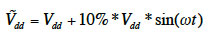
where Vdd =1.8V. Each simulation targets one block for jitter characterization. In other words, the varying power supply is applied solely to the VDD node of the block to be characterized; all other blocks are connected to an ideal DC supply.
Theoretically, to test the validity of the proposed jitter characterization method, two configurations need to be run for each block:
1. A transistor-level simulation with the targeted block in SPICE
2. A mixed-signal simulation with the targeted block in a behavioral model
All other blocks simply stay in SPICE for both configurations.
In the actual mixed-signal simulation setup, an additional configuration (denoted configuration (0)) is necessary. Ideally speaking, since noise-free device models are used for transient simulation, the circuit should be noiseless except for the supply noise. However, there is always noise due to numerical computation errors and it must be accounted for. Hence, a reference configuration, with all blocks in SPICE and all blocks hooked to an ideal power supply, needs to be run for numerical noise floor extraction. Jitter measured from configuration (0) should be deducted from jitters measured from configurations (1) and (2), so that the resulting values of jitter represent solely the contribution from the noise response of the targeted block to the power supply fluctuation. Extracted jitters from configuration (1) and (2) can then be compared, to evaluate the accuracy of jitter characterization using mixed-signal simulation.
In addition, knowing that the VCO output signal switches at the highest frequency and thus is usually the performance bottleneck when it is in analog, we represent the VCO block by a Verilog-AMS model with digital output for all three configurations. The model is calibrated based on a generic model from Mentor Graphics’ QuestaADMS CommLib, as shown in Listing 1. Representing the VCO block in a Verilog-AMS model leads to significant speed-up. As shown in Table 1, the transient simulation of 3ms for the reference run is 18x faster when the VCO is in Verilog-AMS rather than in SPICE. The number of time points is also recorded showing that, when the VCO output is analog, lots of extra ones are needed and the simulation slows down.
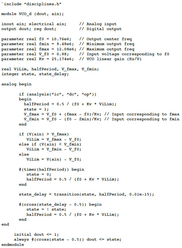
Listing 1
VCO model in Verilog-AMS (calibrated)
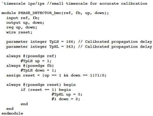
Listing 2
Phase detector model in Verilog (calibrated)
The Verilog-AMS VCO makes a fast characterization and circuit tuning process feasible.
Note that the VCO model in use assumes linear time invariant (LTI) behavior [6]. Its noise conduct will differ from the actual transistor-level design, leading to some compromise in accuracy. However, since the VCO is designed to work in the dynamic tuning range, compromise for the frequency oscillation can be negligible making it a worthwhile trade-off.
Besides, this proposed method is not expected to work for VCO jitter characterization, as VCO responds to fluctuation in the power supply in a time-variant manner that is completely different from gate switching threshold variation.
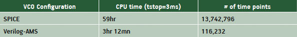
Table 1
Simulation speed comparison for VCO in SPICE against VCO in Verilog-AMS
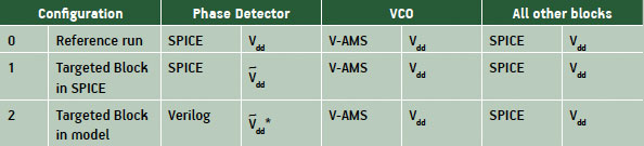
Table 2
Simulation setup for phase detector jitter characterization
Table 2 gives details of the three configurations for jitter characterization of the phase detector block, to further illustrate the simulation setups discussed above. Setup for frequency divider jitter characterization is very similar, except that the phase detector column in Table 2 is applied to the frequency divider instead. In Table 2, there are two columns for each block. The first column shows the block view, either in SPICE or in behavioral model (V-AMS stands for Verilog-AMS). The second column shows the type of power supply applied, where Vdd stands for ideal DC supply and [Equation 4] stands for the power supply with fluctuation. [Equation 5] in configuration (2) stands for the same noisy power supply as [Equation 6] in configuration (1), except that it is applied to the block in a different way. In configuration (1), the phase detector is in SPICE hence [Equation 7] is directly applied; whereas in configuration (2), as the block is a Verilog module instance, [Equation 8] cannot be directly hooked to the block itself, instead, it is applied to the associated analog-to-digital converters, which will be discussed in detail in next section.
Analog/digital converters with dynamic power supply dependency
Aside from behavioral models, another indispensable element for mixed-signal simulations is analog-to-digital converters, which are inserted at analog-digital interfaces to enable mixed-signal interactions.
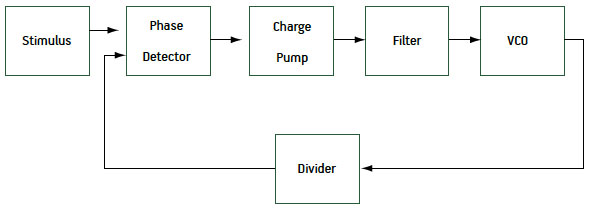
Figure 1
PLL block diagram
Converters are supported by different mixed-signal simulators in different formats and to different degrees of complexity. This paper uses a type of converters carrying dynamic power supply dependency, supported by QuestaADMS [7]. Unlike common converters where Vhi and Vlo as well as the threshold voltage (Vth, or Vth1/Vth2) are set to fixed constant values, this specific type of built-in converter with dedicated dynamic power supply dependency is able to have these parameters hooked to the power supply node instead, such as nodes Vdd and Vss. Consequently, Vhi and Vlo will follow the changes in power supply dynamically, and so will the threshold voltage Vth determined by the tool based on instantaneous values of Vhi and Vlo. This type of converter facilitates the following approach to model the targeted jitter caused by gate switching threshold variation due to power supply fluctuation.
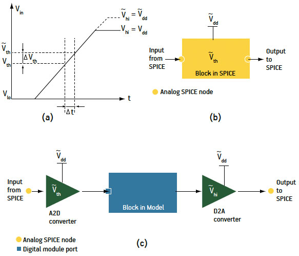
Figure 2
(a) Gate switching threshold variation due to supply fluctuation; (b) Capturing threshold variation when block in SPICE; (c) Capturing threshold variation when block in behavioral model
As shown in Figure 2(a), for a block where the input stage is composed of logic gates, power supply fluctuation in Vdd causes a variation in switching threshold Vth and hence a perturbation, t, in the moment at which threshold crossing is detected, leading to time jitter in the output. When the block is represented at transistor-level in SPICE, the sensitivity of Vth to Vdd intrinsically exists inside of the SPICE circuit itself, as shown in Figure 2(b).
When the SPICE block is replaced by a behavioral model instance with digital ports for mixed-signal simulation, things change. The behavioral model (e.g., a Verilog module for the phase detector as shown in Listing 2) does not include the sensitivity of Vth to Vdd, hence the jitter effect is no longer included in the block itself as it is in its SPICE counterpart. In order to characterize the targeted jitter by mixed-signal simulation, a different channel must be established to capture the jitter effect.
As shown in Figure 2(c), when a SPICE block is replaced by a digital module instance, analog/digital converters (ADC and DAC) are inserted at the input and output ports of the block to interface with other connecting SPICE blocks. These converters are not only essential for feasible mixed-signal simulations, but also provide a channel to capture the targeted type of jitter effect. Assuming a small signal condition applies, the actual Vth dependency on Vdd can be approximated using a simple first-order model. Hence, by taking advantage of the dynamic power supply dependency in the specific type of converters described above, the jitter effect in the actual circuit can be approximately captured by the sensitivity of Vth to Vdd in an ADC. Meanwhile, the DAC that has Vhi sensitive to Vdd helps to convert the digital output accurately to the actual varying supply voltage. As demonstrated below, this approximation allows a considerable improvement in simulation speed at the expense of an acceptable loss in accuracy.
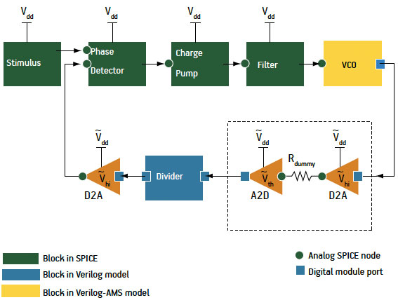
Figure 3
Mixed-signal simulation setup for frequency divider jitter characterization
Note that although the converters used in this paper are built-in converters from a mixed-signal simulation tool, they do not have to be the built-in type. To implement the proposed jitter characterization method, either custom converter models or analog/mixed-signal block models (written in Verilog-AMS or VHDL-AMS) can work as alternatives, as long as the power supply dependency is modeled in. Built-in converters give the best performance though and are most convenient, as they are usually well optimized in terms of performance.
Jitter characterization results
Using the proposed jitter characterization method, the contribution of the targeted type of jitter from the phase detector block in the PLL design is first measured.
The VCO block for this PLL has a center frequency around 10MHz; the division factor is 4; the PLL operates between 1.8V and 0V; and the supply fluctuation applied is a sinusoidal source at 100kHz with peak magnitude of 0.18V (10% fluctuation). Stimulus to the PLL is a reference clock at 2.5MHz with rise time and fall time of 10ns. For accurate jitter measurement, the rise time and fall time of the digital-to-analog converter are set to a very small value of 2ps. Each transient simulation runs for a longstop time of 3ms. Simulations are then performed with tight tolerances.
Table 3 shows the jitter characterization results for the phase detector (PD) block. As in Table 2, three transient simulations with different configurations are performed. Maximum jitter is measured from an eye diagram generated by the VCO output waveform. The reference jitter with an ideal power supply for all blocks is 13.20ns; the simulation with PD in SPICE and a noisy power supply applied to PD gives a jitter of 13.59ns; thus the jitter component from the power supply fluctuation measured from a simulation with PD in SPICE is 0.39ns. Taking the same steps, the jitter component measured from simulation with PD in a behavioral model (Verilog in this case) is 0.41ns.
Comparison shows that the jitter measured from simulation with PD in Verilog is in good agreement with the result from simulation with PD in SPICE (~5%). The CPU time taken for each run is recorded as well, showing that in addition to the 18x speed-up from having VCO in a Verilog-AMS model, an extra speed-up of 3x is obtained with PD in Verilog. This mixed-signal simulation is significantly faster than a pure transistor-level simulation. A similar approach is applied to characterize the jitter from frequency divider as well, with a special setup illustrated in Figure 3.
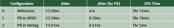
Table 3
Jitter characterization results for phase detector block (PD)
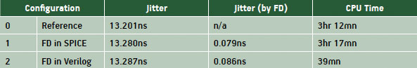
Table 4
Jitter characterization results for frequency divider block (FD)
As discussed earlier, the VCO block is represented by the Verilog-AMS model given in Listing 1, which has an analog input and a digital output. When the divider block is replaced by a behavioral model (in Verilog), if the original block connection in Figure 1 is strictly followed, then the digital input of the frequency divider will be directly connected to the digital output of VCO, without any analog-to-digital converter inserted to help capture the threshold variation in divider block. Hence, to implement the proposed jitter characterization method, a tiny serial resistor of 0.01W (Rdummy) is added between the VCO and divider blocks, as shown in Figure 3, to force the converter insertion in need.
Table 4 shows the jitter characterization results for the frequency divider (FD) block. Taking the same jitter measurement steps as used for the phase detector, jitter characterized from simulation with the FD in Verilog is also in good agreement with the result from simulation with the FD in SPICE as well. The extra speed-up from FD in Verilog is about 5x.
Conclusion
Characterizing PLL jitter via transient simulation is usually hindered by the slow speed of pure transistor-level simulations. This paper has presented a characterization method using mixed-signal simulation instead. Using behavioral models written in Verilog/Verilog-AMS, together with analog/digital converters carrying dynamic power supply dependency, jitter caused by CMOS gate switching threshold variation due to power supply fluctuation is modeled under small signal considerations. This method is applied to the jitter characterization of the phase detector and the frequency divider of a PLL design. Characterization results obtained are close to a transistor-level simulation and the improvement in simulation speed is significant, validating the proposed method as a feasible approach for fast jitter characterization.
This method can be implemented using models written in other behavioral modeling languages as well, and is not limited to the specific type of analog/digital converters used in this paper. Application of this method can be extended to other designs with jitter from gate switching threshold variation as well, such as ring oscillators.
References
[1] K. Kundert, “Predicting the Phase Noise and Jitter of PLL-Based Frequency Synthesizers”, August 2006, http://tinyurl.com/ETFDec10Mentor1.
[2] Maxim Integrated Products, “Application Note 3359, Clock (CLK) jitter and phase noise conversion”, 2004, http://tinyurl.com/ETFDec10Mentor2.
[3] A. Hajimiri, S. Limotyrakis, and T. H. Lee, “Jitter and phase noise in ring oscillators”, IEEE J. Solid-State Circuits, vol. 34, 1999, pp. 790-804.
[4] J. Rabaey, A. Chandrakasan, B. Nikolic, Digital Integrated Circuits: A Design Perspective, 2nd edition, Prentice Hall, 2003.
[5] S. Kang, Y. Leblebigi, CMOS Digital Integrated Circuits: Analysis and Design, WCB/McGraw-Hill, 1999.
[6] T. Lee, A. Hajimiri, “Oscillator Phase Noise: A Tutorial”, IEEE J. Solid-State Circuits, vol. 35, No. 3, March 2000.
[7] Mentor Graphics, QuestaADMS User Manual, Version 2009.2.
Mentor Graphics
Corporate Office
8005 SW Boeckman Rd
Wilsonville
OR 97070
USA
T: +1 800 547 3000
W: www.mentor.com