Bridging from ESL models to implementation via high-level hardware synthesis
The article describes a methodology that bridges the gap between SystemC transaction-level models (TLMs) that are used for architectural exploration and SystemC cycle-accurate models of hardware that typically follow much later in a design flow, after many sensitive decisions have been made.
The behavior of the cycle-accurate models can be verified in the complete system by comparing it with the reference TLMs. The reference model of the complete system then serves as a testbench for the verification and integration of the cycle-accurate models.
This flow allows designers to evaluate alternative architectures early in a project with low modeling effort, and they can integrate cycle-accurate models later on to progressively replace the TLMs.
Exact timing and performance properties obtained from simulating cycle-accurate models (e.g., power consumption, resource load) are used to back-annotate the reference models. This increases the level of confidence in decisions made when exploring the design space.
The methodology is illustrated via a case study involving a JPEG system, using Mentor Graphics’ Catapult Synthesis and CoFluent Design’s CoFluent Studio tools to provide a complete ESL flow, from architectural exploration to hardware implementation.
Cycle-accurate models very precisely predict the behavior and performance of hardware and software components. Behavioral and performance transaction-level models (TLMs) enable hardware/software partitioning decisions to be made at the electronic system level (ESL) early in the development phase, long before cycle-accurate models will be available. The problematic gap between these different types of models is known as the ESL implementation gap.
Figure 1 offers a proven methodology that bridges the gap from SystemC TLMs for architectural exploration to SystemC cycle-accurate models of hardware. The behavior of the cycle-accurate models can be verified in the complete system by comparing it with the reference TLMs. The reference model of the complete system serves as a testbench for the verification and integration of the cycle-accurate models.
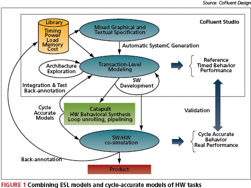
This flow allows designers to evaluate alternative architectures early in a project with low modeling effort, and integrate cycle-accurate models later on to progressively replace the TLMs. Exact timing and performance properties obtained from simulating cycle-accurate models (e.g., power consumption, resource load) are used to back-annotate the reference models. This increases the level of confidence in decisions made when exploring the design space.
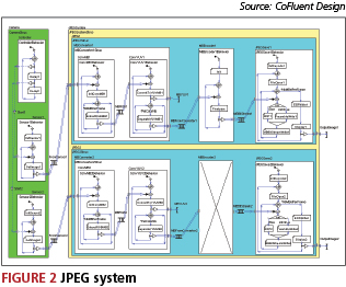
JPEG system application modeling
A JPEG system will be used to demonstrate the design flow. It consists of a still camera and a JPEG encoder/decoder (Figure 2). The Camera includes a Controller and two image Sensors. The JPEG encoder/decoder consists of two subsystems (JPEG1 and JPEG2), each processing the images acquired by a sensor. The subsystems consist of three functions: MBConverter, MBEncoder and JPEGSave. The structures of the two subsystems are different for MBEncoder. The test case focuses on the transaction-level and cycle-accurate modeling of the MBEncoder1 and MBEncoder2 functions, the mapping of these functions onto a multiprocessor platform, and the resulting performance of multiple candidate architectures in terms of latency, utilization and power consumption.
MBEncoder1 is modeled with one computational block (Pixelpipe), as shown on the left of Figure 3. This function contains the entire JPEG sequential C code, which constitutes the reference algorithm tested on a PC.
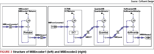
MBEncoder2 has the same functionality as MBEncoder1. The difference is the granularity: MBEncoder2 is more detailed in order to optimize its implementation, as shown on the right of Figure 3. The separation enables the optimization of image processing by introducing parallelism in the application. Mapping these functions onto a hardware or software processor enables the exploration of their behavior and performance.
Functional TLMs of the encoders
In the TLMs of the encoders, the behavior of the Pixelpipe, DCT, Quantize and Huffmanize blocks is implemented by calling procedures that execute sequential C code provided by Mentor Graphics. This C code operates on algorithmic C bit-accurate data types. These allow you to anticipate the replacement of the reference model with the cycle- and bit-accurate model obtained after the hardware undergoes high-level synthesis with Mentor’s Catapult C software.
These are the execution times measured in CoFluent Studio for the functions under consideration.
| Computation block | Average execution |
| DCT | 25.40us |
| Quantize | 26.09us |
| Huffmanize | 113.60us |
|
Pixelpipe |
152.06us |
These numbers are obtained by calibrating the execution of the application on a 1GHz PC. The measurements provide initial timing information that is precise enough to map the corresponding functions onto software processing units (e.g., CPU, DSP). To map these functions onto hardware processing units (e.g. ASIC, FPGA), more accurate numbers can be obtained from high-level hardware synthesis.
Although the execution time of Pixelpipe is shorter than the sum of the execution times of DCT, Quantize and Huffmanize, the processing of a complete image is shorter with MBEncoder2 (439ms) than with MBEncoder1 (536ms). This is because the DCTMB, QuantizeMB and HuffmanizeMB functions are pipelined, whereas MBEncoder1 has to complete the processing of a macro-block before accepting a new one. Also, the processing speed of the pipeline in MBEncoder2 is limited by the HuffmanizeMB function, since it has the longest execution time in the pipeline.
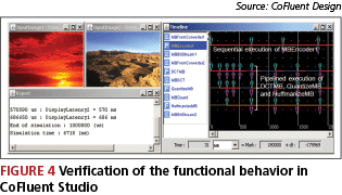
The operations are verified by visualizing images in CoFluent Studio and reviewing the timing properties as shown in Figure 4. Simulating one second of data with the parallel processing of two images of 200×128 pixels at the transaction level requires only a few seconds of actual simulation time.
Platform modeling
The complete JPEG application is mapped onto the platform model shown in Figure 5. It consists of an ExternalPlatform, modeled as a hardware processing unit, and a JPEGPlatform.
CoFluent Studio offers generic models of hardware elements. These processing, communication and storage units are characterized by high-level behavioral and performance properties that are parameterized to represent physical parts. Multiple and various platform models can be described quickly, without investing in the expensive development or acquisition of models of specific IP components, such as memories, buses or processors. Simulation of software is not based on instruction-set simulators, as the C code used to describe algorithms executes natively on the simulation host.
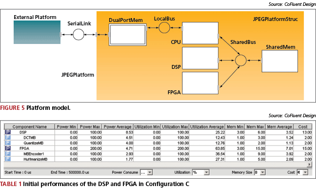
The FPGA has a speed-up defined as a generic parameter named FPGA_SpeedUp, which can vary from 1 to 250, with a default of 10. This parameter represents the hardware acceleration. The speed-up of the DSP is set to 2, meaning that the internal architecture of the DSP is twice as efficient as a general-purpose processor, due to specialized embedded instructions.
The test case maps MBEncoder1 and MBEncoder2 onto the FPGA and DSP, with exploration of multiple mapping alternatives. The following assumptions were used: the Camera model is mapped onto the External platform, while MBConverters and JPGSave are mapped onto the CPU with execution times short enough not to delay the DSP and FPGA.
Average execution times can now be updated a follows:
| Computation | SW execution | HW execution |
| block | (KCycles) | (KCycles) |
| DCT | 25.40/2 | 25.40/FPGA_SpeedUp |
| Quantize | 126.09/2 | 26.09/FPGA_SpeedUp |
| Huffmanize | 113.60/2 | 113.60/FPGA_SpeedUp |
|
Pixelpipe |
152.06/2 | 152.06/FPGA_SpeedUp |
The power consumption for each computation block is described using a simplified law that utilizes the FPGA_SpeedUp parameter. A higher speed-up on the FPGA uses more gates, and therefore increases the power consumption. The power consumption equations are:
| Computation Power | block consumption (mW) |
| DCT | 0.2*FPGA_SpeedUp^(3/2) |
| Quantize | 0.15*FPGA_SpeedUp^(3/2) |
| Huffmanize | 0.2*FPGA_SpeedUp(3/2) |
| Pixelpipe | .25*FPGA_SpeedUp^(3/2) |
Mapping and architecture modeling
Architecture description
One image is imposed every 500ms simultaneously to MBEncoder1 and MBEncoder2. Here is a comparison of the performance of the three configurations.
| Function | Config. A | Config. B | Config. C |
| MBEncoder1 | FPGA | DSP | FPGA |
| DCTMB | DSP | FPGA | DSP |
| QuantizeMB | DSP | FPGA | DSP |
|
HuffmanizeMB |
DSP | FPGA | FPGA |
By studying the impact of FPGA_SpeedUp on the performance of the system in terms of latencies, resource utilization and power consumption, the best architecture and the minimum value required for the FPGA_SpeedUp generic parameter can be selected.
CoFluent Studio’s drag-and-drop mapping operation is used to allocate functions to processing units and route data through communication channels. The resulting architectural models are automatically generated in SystemC.
Profiling data is automatically collected for each configuration at all hierarchical levels during simulation. The simulations are based on individual properties, described using constants or C variables. This information is displayed in tables, as shown in Table 1. The utilization of the FPGA increases to 200% because two functions (MBEncoder1 and HuffmanizeMB) can be executed in parallel on the FPGA.
Initial exploration results
Early exploration results are based on initial timing properties measured by simulating the reference model. Results in terms of utilization and power consumption on the DSP and FPGA, and processing latencies for the two JPEG encoders/decoders, are given for the default case (FPGA_SpeedUp = 10). Configuration C processes both images with the shortest latencies.
| Config. A | Config. B | Config. C | ||
| Latencies (ms) | Path w. Encoder1 | 182 | 366 | 182 |
| Path w. Encoder2 | 400 | 136 | 136 | |
| Utilization (%) | DSP | 80.01 | 73.23 | 25.22 |
| FPGA | 36.64 | 39.77 | 63.85 | |
| Power Cons. (mW) | DSP | 30.60 | 33.09 | 8.53 |
| FPGA | 2.93 | 2.55 | 4.71 |

Figure 6 shows that, on average, Configuration C consumes less power than the two other configurations. However, the power consumption on the FPGA is higher for Configuration C.
In CoFluent Studio, it is possible to explore the impact of generic parameters at the system level for multiple architectures with a single simulation. The results for all configurations are collected and displayed in the same environment. This allows for rapid comparison of architecture.
Figure 7 shows the impact of FPGA_SpeedUp on latencies and power consumption. For Configuration C, MBEncoder2 becomes the bottleneck, since the system performance is limited by the DSP. The simulations show that FPGA_SpeedUp = 15 is the minimum and optimal value, and should be set as the objective for the hardware high-level synthesis tool.
Calibration of the reference model
In the previous section, the JPEG system was modeled at the transaction level, and system-level decisions were made based on the initial exploration results. In this section, cycle-accurate models obtained from Catapult C hardware high-level synthesis are integrated back into CoFluent Studio for further verification and refinement.
Functional cycle-accurate models
Using Catapult C, the sequential C code that is executed in the computation blocks is converted into SystemC cycle-accurate code. The resulting code is integrated back into CoFluent Studio to verify the behavior of the cycle-accurate models against the reference TLMs. Then, the timing and performance properties of the cycle-accurate models are extracted through simulation to calibrate the architecture exploration process for functions that are mapped onto hardware units.
In order to integrate the cycle-accurate models back into CoFluent Studio, SystemC wrappers are created (Figure 8). They convert incoming transaction-level data to cycle-accurate data that is processed by the detailed model, and vice versa. The wrappers handle interfaces and protocols specific to the detailed model, such as handshakes and memories.
It took one day to wrap the detailed models and integrate them into CoFluent Studio. The verification task is simplified since the reference TLM is used as a testbench. The processing of macro-blocks and images can be displayed directly in CoFluent Studio. However, the simulation speed is slower. For this example, it is approximately 400 times slower than the transaction-level simulation.
These are the exact properties of the cycle-accurate operations in terms of the (measured) number of clock cycles and the (assumed) power consumption.
| Average exec | Average power | |
| Function | (clock cycles) | cons. (mW) |
| DCTMB | 161 | 1000 |
| QuantizeMB | 72 | 800 |
| HuffmanizeMB | 576 | 1200 |
|
MBEncoder1 |
303 | 1400 |
The back-annotation of the timing information leads to more accurate performance results during the design-space exploration phase.
As in the reference model, HuffmanizeMB is the slowest function in the pipeline in MBEncoder2. This is due to the fact that the cycle-accurate model of the HuffmanizeMB function does not read/write elements of a macro-block continuously whereas the three other models do.
Performance analysis after calibration
In order to explore the performance of the same architectures, the reference model is back-annotated with exact properties of the detailed models. Since timing properties are exact, the value of the FPGA_SpeedUp parameter is set to 1 for this new iteration in the architecture exploration phase.
|
Config A |
Config B |
Config C |
||
|
Latencies (ms) |
Path with Encoder1 |
6 (7) |
366 (366) |
6 (7) |
|
Utilization (%) |
DSP |
80.01 (80.01) |
73.23 (73.23) |
25.22 (25.22) |
|
Power. Cons. (mW) |
DSP |
30.60 (30.60) |
33.09 (33.09) |
8.53 (8.53) |
| TABLE 2 Exploration after synthesis and back-annotation | ||||
As shown in Table 2, the speed-up obtained after high-level synthesis is approximately 250. Values obtained based on the reference model for FPGA_SpeedUp = 250 are indicated between brackets for comparison. The metrics of interest converge toward similar values from the reference model for all architectures, confirming design decisions made early, based on the reference transaction-level model.
Configuration C leads to the shortest latencies. As predicted with the reference transaction-level model, the bottleneck for Configuration C is the DSP, since the real speed-up exceeds 15. Configuration C permits each encoder to process two images in parallel every 126ms. As shown in Figure 9, this leads to a peak power consumption of almost 1W on the FPGA. For comparison, the dynamic profiles returned by the reference model with FPGA_SpeedUp = 15 are also shown. The configuration with FPGA_SpeedUp = 15 can process the same number of images, with a lower peak power consumption (approximately 25mW).
Maximizing encoding performance
By optimizing the latencies in the back-annotated model by mapping both MBEncoder1 and MBEncoder2 onto the FPGA, the DSP limitation is avoided. In this configuration, two images can be processed in parallel in 9ms: each encoder processes more than 100 images per second. The resulting average power consumption is higher than 1.6W on the FPGA. Figure 10 shows the case where the two encoders receive an image every 10ms.
The exact durations of the detailed models are indicated in Figure 10; highlighting the bottleneck is the HuffmanizeMB function in the pipeline. This function must be synthesized differently to reach the execution time of 3030ns of the MBEncoder1 function, leading to approximately 150 images per second.
Conclusion
Joining TLMs and cycle-accurate models obtained after high-level hardware synthesis using Mentor Graphics’ Catapult C Synthesis for architecture exploration in CoFluent Design’s CoFluent Studio, provides a complete ESL flow, from architectural exploration to hardware implementation. With the ‘implementation gap’ closed, designers can benefit from the architectural exploration and profiling completed early in the design cycle.
The design compared the utilization ratio (resource load), processing latency and dynamic and average power consumption of the three configurations. Generic parameterized models of platform elements and the drag-and-drop mapping tool allow quick completion of initial architectures. Once the impact of a generic parameter that represents the hardware acceleration was analyzed, the minimum value required for that parameter to optimize both latencies and power consumption was found.
Reference C algorithms are converted to SystemC cycle-accurate models using the Catapult C synthesis tool. The resulting cycle-accurate models are integrated back into CoFluent Studio to refine the TLMs for those functions that map onto hardware processors. Wrapping SystemC around cycle-accurate models enables the transaction-level models to interface with cycle-accurate models. The behavior of the wrapped, detailed models was verified within CoFluent Studio against the behavior of the reference model, which served as a testbench.
Back-annotated timing properties of the reference TLM are based on exact timing obtained by simulating the detailed models. The back-annotated model is used to explore the same architectures as with the reference model. Reaching the same conclusions confirms that decisions can be made early and with a high level of confidence based on the reference transaction-level model. This also confirms that external SystemC models—hand-written or synthesis result—can be easily integrated into CoFluent Studio, but cycle-accurate models should only be used for validation and calibration, and be replaced by their transaction-level equivalent models to maintain simulation efficiency.
Acknowledgements
The author would like to thank Thomas Bollaert from Mentor Graphics for providing the sequential C code of the JPEG application as well as for the four detailed models generated using Catapult C.
CoFluent Design
24 rue Jean Duplessis
78150 Le Chesnay
France
T: +33 139 438 242
W: Cofluent Design portfolio (now part of Intel)