Advanced RTL power-aware verification
Traditional verification tools struggle to deal with today’s increasingly sophisticated power management technologies. One major limitation is that they cannot deal with varying power states because they make a built-in assumption that devices are always fully powered on. Further, power-aware verification at the register-transfer level is proving increasingly problematic, although it is also becoming increasingly important as design schedules demand that problems are identified and addressed as early as possible.
Engineers from Texas Instruments describe their experiences with the Questa verification software from Mentor Graphics that seeks to overcome these problems.
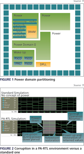
The ever-increasing complexity and performance requirements of SoCs and the leakage characteristics of advanced deep-submicron ASIC processes have made advanced power management increasingly common (Figure 1). Yet until recently, no tool could verify a system at the RTL with respect to different power supply levels.
Some verification has been possible at the gate level using post-physical design gate netlists that model the effects of power management techniques. Static verification tools also exist (e.g., Spyglass, Conformal Low-power) and these can catch a number of bugs at various levels of abstraction. However, they typically cannot catch problems associated with a system’s dynamic behavior.
This is why it is not just important but mandatory that engineers verify a design with power information in a dynamic fashion and, as much as possible, at the RTL. Put simply, power management verification must occur early in the design cycle if designers are to minimize the impact of any bugs on project deadlines.
Traditional RTL simulation environments incorporate no concept of power because the simulator itself assumes the whole design is always powered-on. By contrast, the Questa tool from Mentor Graphics directly addresses today’s more complex power environments and offers a signal corruption technique in the RTL simulation context. The simulator mimics the behavior of a design (including both power management and non-power management cells) when the power supply is turned off and on, corrupting or not corrupting various design elements. 
Figure 2 captures the contrast between traditional verification and the power-aware RTL stage that is needed, while this article describes practical methods used to verify the power-management implementation of a complex TI SoC using Questa. We will demonstrate how to use the software’s complete feature set and leverage most of the improved functionality of its power-aware engine.
The design
The case study features a recent TI ASIC developed in collaboration with a major wireless customer to implement a 3G application. The work was relatively successful—a number of bugs were detected at RTL that would have passed through a traditional verification flow until late in the layout and might even have reached silicon.
The architecture of the design-under-test (DUT) was split into several power domains that could be switched off or on independently. Part of the logic always had to be powered-on to initiate power-down and wake-up sequences. Some always-on power domains required retention, which meant that the states of some registers were maintained even when the surrounding logic was no longer receiving power.
Finally, there was a requirement whereby many different combinations of clock states and frequencies, as well as of power-domain levels and voltage values, needed to be able to execute in a consistent fashion in order to achieve best functionality, performance and power consumption.
The power-aware flow
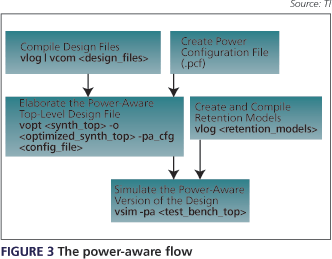
The basic steps in our power-aware simulation flow—also shown in Figure 3—are:
- Create a tool configuration file—a.k.a. a power configuration file (PCF)—that accurately describes the power-management structures in the design (e.g., power elements/domains, retention elements and their control signals).
- Create Verilog models that describe the retention behavior of the sequential elements, and compile them.
- Generate the power-aware, Verilog, top-level design file (mspa_vopt.v) that infers the sequential elements. This is done by running the Questa elaboration vopt command on the previously compiled design, using the PCF.
Run simulations, adding the Questa –pa argument in the command line and using the regular testbench with the generated mspa_vopt.v module.
Configuring the flow
The following three elements form the basis of the power configuration file:
- the corruption mode
- the retention definition (if needed)
- the always-on logic declaration
One of the first decisions concerns how you write the PCF. You have the option to build a single, unified PCF for the whole chip or several files—one per power domain. Which one you use depends on the design’s complexity, the number of power domains, and how the project is divided across the team. If parts of the design come from several intellectual property (IP) sources, it can be helpful to integrate existing PCFs by including a command line in the top one.
We explored both options. We used a single PCF in a medium-complexity design with a limited number of power domains where the verification team had a good understanding of the IP various blocks. We used multiple PCFs in a more ambitious project that included many power domains and where we did not have detailed knowledge of the IP. In the latter case, the PCFs were created by the IP teams and integrated by the verification team at the top level. To this end, we created an integration methodology that leveraged the usage of variables through the power-aware flow.

Corruption modes
In formal terms, ‘corruption’ denotes the temporary or permanent change of a signal from its current value to an ‘X’ value due to power disruption. Three corruption modes exist: output-only corruption, output and sequential corruption, and full corruption.
Until recently, the output-only mode was mostly used within TI. Here, power domains or hierarchical entities within one power domain have their outputs corrupted whenever the related domain is switched off. The actual cells within the domain are not modeled power-wise. This is simple and easy to use, but not completely accurate, particularly where there are elaborate retention schemes.
Output and sequential corruption is a more accurate and representative mode. It better models power management structures down to the cell level. Corruption is applied directly not only at the outputs of the power domains, but also for every embedded sequential element (e.g., a retention flip-flop and retention latch (RFF/RLA)). So when the power—specifically, the evaluation of the power control signals—corresponding to a power element is off, the power element value is corrupted. When the element is (or contains) a RFF/RLA, the retention behavior is modeled as mapped in the PCF.
Full corruption not only corrupts the outputs and the sequential elements but also the wires. It is the most realistic mode because even the internal signals are corrupted. However, it must be used carefully as modules can be easily corrupted unintentionally.
Retention
When power is off, the data registered in sequential elements may need to be maintained. Questa allows the user to define the processes to be retained through the mapping of a statement. You tell the tool the region to which the retention will be applied, the retention control signal, and the power-aware behavioral model that has to be mapped.
On this last point, Verilog models describing the various retention elements (flip-flop or latch) must be compiled specifically for the power-aware simulation. The model types depend on the real cell type inferred in the design. Typically, the selection varies between registers that are active on positive or negative edges.
A good practice to validate the definition of the retained sequential elements in the PCF is to crosscheck power-aware simulation results with synthesis results. It is useful to modify the PCF if needed and progressively increase its accuracy.
Always-on logic
Finally, the correct behavior of power-down and wake-up sequences requires always-on modules and signals. These are mainly linked to logic relative to power, interrupt, clocks, reset, and so on. The always-on logic has to be declared using the same kind of statement as corrupted logic except there is no power signal.
Test case selection
A suitable set of simulation test cases must be used to properly exercise the desired features and detect potential failures. The set must cover all possible power management scenarios. It must contain power-down and power-up sequences for all of the power domains to be verified in the ASIC—the minimal version will includes the boot-up sequence, some cycles in normal mode, an idle request, a low-power mode sequence (e.g., sleep, off, etc.), a wake-up from low-power mode, and some checks.
Typical defects found
The goal of these simulations is to catch as many power-management implementation issues as possible at the RTL. Typical issues here include:
- isolation (isolation cells instantiation);
- retention elements (registers and latches);
- resets;
- power sequencing (power reset and clock management modules); and
- always-on paths.
By running dedicated power-aware test cases in the power-aware flow, we were able to catch critical bugs, including these examples:
- An isolation signal was misconnected during the power management integration. This would have prevented reset signals from being correctly propagated to the CPU. In non-power-aware simulations, the CPU wrongly resumed execution instead of rebooting. In power-aware-simulations, it crashed due to internal corruption.
- After a full power-down, the chip was woken up by a given event. At this point, some particular, retained status registers within the power management controller module containing a switchable power domain should be reset. In a non-power-aware environment, the reset was correctly applied to this register because this power domain was kept ‘on’ and there was no corruption. In a power-aware-environment, this retention register was corrupted and the reset line was forced to ‘X’ during the chip power-down. Since this reset was asserted while the switchable power domain was ‘off’, but released before it was turned ‘on’, the status register was not reset and the retention value was restored at power ‘on’.
By adding SystemVerilog assertions within the various Verilog retention flip-flop models, we discovered several significant power signal sequencing issues, such as functional clock activity during the isolation and retention phases that is normally forbidden.
Issues and limitations
Modeling limitations
The PCF must represent the exact power management structure of the design. So, it must be written by someone who has a global knowledge of the different techniques implemented, a good understanding of the power controller module, and a general overview of the design, its critical IP and signals. You must also check that the PCF syntax is accurate and correctly understood by the tool.
The non-power-aware behavioral models used for RTL simulations may have to be excluded, as it may be impossible to correctly constrain them. The same goes for models available only in a gate-level environment as the power-aware engine will not interpret these.
Tool issues
The main issues we encountered were during the power-aware, top-level Verilog file generation step (mspa_vopt.v). Indeed, due to tool maturity issues, some HDL syntaxes and more particularly, instances of HDL auto-generated code, were not well understood. Therefore, some sequential elements were ignored and not corrupted during the power-aware simulation, lowering our confidence in the chip verification.
The future
Given the ever-increasing prevalence of power management in ASIC designs, the power-aware simulation strategy described in this article should yield direct benefits for a wide range of verification engineers.
We also identified several enhancements related to corruption, syntax analysis and latch modeling that are being implemented in the upcoming versions of the Questa tool.
Texas Instruments
BP 5
06271 Villeneuve-Loubet Cedex
France
T: +33 (0) 493 22 20 01
W: www.ti.com