A holistic approach to low-power verification
The article describes a dedicated low-power functional verification methodology, originally developed at STMicroelectronics (now ST-Ericsson). The article details the content, sequence and effectiveness of the methodology as it was tested on a 45nm system-on-chip design.
In order of use, the main components are:
- A high-level verification language testbench
- Formal verification
- Rule checking
- C function library and tests
- Assertion-based verification
From 90nm, the exponential nature of leakage current in the sub-threshold regime of the transistor has become a major concern—it constitutes over 40% of total power expenditure at 65nm. The use of innovative design techniques to overcome leakage has created new challenges for verification that demand a creative response.
There is no verification panacea here. No individual tool can sufficiently verify all the tricky issues engendered by today’s low-power techniques. Therefore, our team combined several different strategies according to their relative strengths in a comprehensive functional verification methodology that accelerates the design process while still ensuring that we meet our low-power verification goals.
We applied this methodology to verifying the low-power implementation of a multi-CPU 45nm design. This case study discusses the thinking behind the components in the methodology, its general effectiveness, and its success in catching bugs.
A low-power architecture
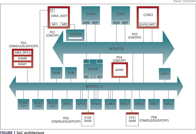
The MAG45-Lite SoC (Figure 1) was developed primarily to explore 45nm low-power techniques so we could establish a standard tool chain for future projects. To exercise both front-end and back-end low-power flows, we defined seven power domains and four power states: ‘ON’, ‘IDLE’ (all supplies biased), ‘SLEEP’ (all biased except normal logic) and ‘OFF’. Source biasing required both input isolation to prevent input toggling and a conditional corruption capability within the power-aware simulator. 
Paying more attention at the design stage to simplifying verification may minimize the risk of introducing low-power-related bugs. Some examples:
- Keep the system controller FSMs used to drive the power domain control sequence signals identical, regardless of the power domain. Unwanted signal outputs may simply be left unconnected.
- Minimize the number of power states and transitions.
- Clearly identify the power state within the power controller.
- Add input isolation to all power-down modes, if any biasing is used, to avoid debugging additional decode logic.
- Adopt a coherent and consistent signal naming policy to allow automatic signal mapping for the assertions.
A comprehensive low-power verification flow
Before undertaking any verification, a plan identified principal areas of concern:
- seven power islands;
- four power modes and the transitions for each;
- the correctness of power-down functional effects (logic corruption in ‘OFF’ and ‘SLEEP’; retention for ‘IDLE’ and ‘SLEEP’ only);
- biasing effects;
- the correctness of low-power entry/exit sequences;
- power sequence independence;
- behavior in all modes of regular logic, retention memories, and retention flip-flops;
- input and output isolation, along with output values; and
- system verification (power operating modes)
Our goal was to detect bugs early in the design cycle and avoid costly delays. We used a complementary test plan to detail how the verification plan was structured. Our ultimate purpose, though, was to find and develop the most efficient techniques using state-of-the-art tools.
We wanted our methodology to be vendor-independent where possible, while maximizing reuse between the power domains and also between projects. Based on our experience, we propose performing the different verification strategies in the following order:
- High-level verification language (HVL) testbench
- Formal verification
- Rule checking
- C function library and tests
- Assertion-based verification (ABV)

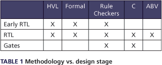
Table 1 also shows which verification strategy should be applied at different stages of the design.
HVL testbench
The HVL testbench provided stimuli to check bus access, program power-down and power-up sequences, and correct functionality after power restoration. The HVL testbench is particularly suited to the early stages of a project, before the availability of CPU models or C tests.
We used commercially available verification components to model registers, memory and AXI masters. Each AXI master was replaced by its equivalent verification component to permit the testing of SoC bus connections, register read/write accesses and memory map validation. CPU bus access to all power domains and all low-power-related registers was thus assured.
All of these tests can be easily performed randomly, and automatic functional coverage indicates when 100% functional coverage is achieved.
Formal verification
Formal verification then checked signal connections between the power controller and the switch controllers within the power domains. It is proving to be increasingly popular in relation to low power and should be seen as complementary to dynamic methods.
Because the system controller block is of primary importance for the control of all resets, clocks and power sequence signals, it is the only block verified at the intellectual property (IP) level. Code coverage and qualification metrics were obtained to ensure a desirable level of quality.
Formal verification was also used to verify signal connections between the power controller and the power domains. The verification of all 218 connections took only a few seconds and this positive result guaranteed the independence of all power domains. This approach lends itself well to the early stage of a project.
Code checkers
We ran code checkers at the RTL, synthesis and back-end phases. They included RTL coding style, sleep connection correctness, correct use of retention flip-flops and retention memories, comprehensive isolation checks and sequence checking.
These checks may be performed at the various levels cited, depending on when the dedicated low-power logic is inserted. They are for the most part structural tests. The goal again is to find bugs as early as possible. There is some basic support for low-power sequence checking, though the technology is still immature. Ideally, we would like to statically verify low-power sequences.
C function library and tests
We defined a set of generic C functions relating to the power sequences and to power domain accesses on which all test writing could be based. These functions manage all of the possible power modes, mode transitions and control types used (e.g., HW, FSM/SW, registers/external), for which many combinations were possible. This led to faster test writing, more easily understood tests, and quicker debug as the tests focused exclusively on low power.
As the functions were predefined, test templates were created from which all the tests could be automatically generated by scripts. Each test template is readily reusable and understandable.
A conclusive trial was also run using graph-based techniques that had the advantage of avoiding user-developed scripts. However, the use of C code is insufficient to verify all low-power aspects of a design. It is limited to checking retention (e.g., in memories, retention flip-flops, ordinary logic) and bus error (APB, AXI) responses.
ABV
Finally, ABV was employed dynamically with a power-aware simulator to ensure the correctness of the power control sequences and of the isolation blocks. We used Property Specification Language (PSL) Verilog assertions for portability reasons. PSL assertions complemented our C tests by ensuring that all other issues were treated. Furthermore, they served as functional coverage items for the low-power sequences. Assertions are passive and play no part in stimulus generation.
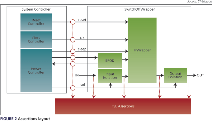
Assertions may be placed directly in the RTL of the IP or, alternatively, they can be positioned in a ‘vunit’ container at the testbench level. When added to the RTL, the main advantage is that assertions can be used in verification from the IP through to the SoC level. However, if a block of IP is externally sourced, the RTL may not be modifiable. To overcome potential restrictions, signal mapping functions within the simulator allow probing signals to be hidden deep within the hierarchy and mapped to signals anywhere in the design (though typically somewhere in the testbench). Figure 2 shows where the assertions probes are positioned. 
To reduce the workload, generic assertions were written where possible. The script then produces all the necessary assertions using the generics and a configuration file that lists all the signals to be checked (or provides an entity to be parsed). To help this process, the signal naming policy across the isolation blocks and the IP must be coherent to avoid manual signal mapping and assertion writing. You should adopt such a policy at the beginning of a project. 
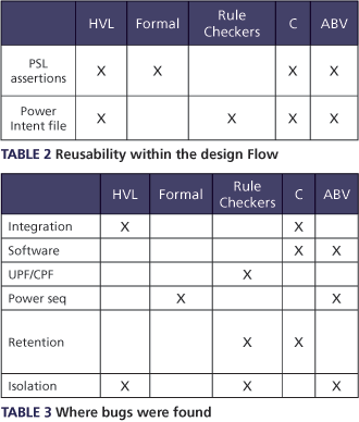
Two low-power specific files were developed for verification: PSL assertions and the power-intent description file—they can be produced in the Common Power Formator the Unified Power Format. Table 2 shows their reuse across various verification flows.
Bugs found
Table 3 summarizes the design areas where specific types of typical low-power design bugs were found with each verification technique. The single most important technique was ABV in conjunction with a power-aware simulator.
In the case of HVL, no bugs were found outside of integration or isolation errors since we did not run any software, power intent files, or low-power tests with it. As formal verification was run late in the project, all potential bugs capable of being found with this method had already been unearthed, so these results should not detract from HVL’s suitability.
For brevity, we provide only one example of each error type:
- Integration errors: an incorrect CPU architecture was detected using C tests at the RTL.
- Software errors: sequence order changes not updated in the software were detected using assertions at the RTL.
- Power-intent file errors: syntax errors were found using a side file parser/analyzer early in the RTL stage.
- Power sequence errors: PSL assertions allowed us to detect illegal power mode transitions due to erroneous software-controlled sequences.
- Retention errors: retention in an ‘OFF’ state was identified at the RTL.
- Isolation errors: incorrect isolation value settings were detected during the early RTL phase using rule checkers.
Verification assessment
The comprehensive blend of verification methodologies tested during this project proved robust and efficient at finding bugs early in the cycle. All were detected no later than the RTL. Gate-level verification gave added reassurance that no clock or start-up issues might prevent first-time silicon success.
In the early phase, static verification was a valid alternative to simulation for checking connections and was quick to set up and run.
The fastest way to develop PSL was to work with pre-saved waveforms and derive a testbench directly from them. This avoided a time-intensive, compilation-elaboration-simulation cycle for correcting simple PSL syntax errors. Debug iteration times were thus reduced.
Drawbacks with our methodology included the need for many PSL assertions, a large simulation size, and long debug iteration times. Fortunately, approximately 90% of the PSL assertions were isolation-related and most will become redundant through the use of automatic isolation insertion within power intent files. At the beginning of the project, this technique was not validated, though it was available.
A lot of verification information may be retrieved from the power intent file and used to generate automatic test plans, assertions, low-power tests, and, of course, functional coverage targets. EDA tool suppliers are now moving in this direction, which will go a long way toward improving the quality of low-power designs and the productivity of the verification effort.
ST-Ericsson
39 Chemin du Champ-des-Filles
CH 1228
Plan-les-Ouates
Switzerland
T: +41 22 929 29 29
W: www.stericsson.com