Using Open Virtual Platforms to build, simulate and debug multiprocessor SoCs
The Open Virtual Platforms (OVP) initiative aims to help resolve the difficulties that arise today when modeling multicore systems-on-chip (SoC) so that designers can perform early and timely test of the embedded software that will run on the end devices.
As architects continue to add more cores to meet hardware design goals, the complexity of embedded software continues to increase exponentially because of factors such as amplified software concurrency and shared on-chip resource bottlenecks.
The OVP-based platform enables early software test through powerful simulations that execute at hundreds of MIPS, that are aimed specifically at the challenge posed by multicore, and that incorporate appropriate application programming interfaces (APIs) for the modeling of processors, components and platforms.
This paper reviews the construction of a multicore SoC platform, describes how to simulate the platform and how to connect it to a debugger.
The Open Virtual Platforms (OVP) initiative addresses problems embedded software developers face when modeling the system-on-chip (SoC) that will host their program. These range from modeling architectural complexity to a lack of open resources for building platforms, to insufficient simulation speeds for software verification.
Embedded software programming issues introduced by the move to multicore processing are now the most significant problems facing SoC delivery. As architects add more cores, embedded software complexity increases exponentially because of amplified software concurrency and shared on-chip resource bottlenecks.
One answer is to comprehensively test software early in the design flow on a simulation that can handle SoC complexity and deliver the performance to verify billions of operational ‘cycles’. The solution must permit model interoperability and the use of legacy models to reduce integration risks and costs. End-users, tool and intellectual property (IP) developers, and service providers must be able to contribute to the platform development infrastructure.
The OVP-based platform satisfies these criteria by enabling software simulations that execute at hundreds of MIPS. It handles multicore architectures, and has a robust set of application programming interfaces (APIs) for the easy modeling of processors, components and platforms. An open source modeling approach enables the community to drive further technology development and leverage existing work.
This paper details how to build a multicore SoC platform, and describes how to simulate the platform and connect it to a debugger. The development of specific processor, behavioral and peripheral models with the OVP APIs is left to another paper.
Specifically, this paper describes using the Innovative CPUManager (ICM) API to implement simulation models of platforms that contain any number of processor models communicating with shared memory. Platforms created using the ICM interface can be simulated using either the free OVPsim simulation environment or a commercial product available from Imperas. OVPsim (available to download at www.OVPworld.org)
is a dynamically linked library implementing Imperas simulation technology. It contains implementations of all the ICM interface functions described in this article. These functions enable the instantiation, interconnection and simulation of complex multiprocessor platforms containing arbitrary local and shared memory topologies.
For Windows environments, MinGW (www.mingw.org) and MSYS should be used. At Imperas, we currently use gcc version 3.4.5 with MinGW runtime version 3.14 for Windows. OVPsim is currently available only on Windows XP.
The examples in this paper use the OR1K processor model and tool chains, also available at www.OVPworld.org.
Single processor platform
A simple program can be made that runs a single-processor platform using just five routines from the ICM API:
- icmInit This routine initializes the simulation environment prior to a simulation run. It should always be the first ICM routine called in any application. It specifies attributes to control some aspects of the simulation to be performed, and also specifies how a debugger should be connected to the application, if required.
- icmNewProcessor This routine is used to create a new processor instance.
- icmLoadProcessorMemory Once a processor has been instantiated by icmNewProcessor, this routine is used to load an Executable and Linking format (ELF) file into the processor memory.
- icmSimulatePlatform This routine is used to run simulation of the processor and program for a specified duration.
- icmTerminate At the end of simulation, this routine should be called to perform cleanup and delete all allocated simulation data structures.
The example uses the OR1K processor. This can be found online at http://www.opencores.org/projects.cgi/web/or1k/architecture. The test platform source constructs a simple single-processor platform in the main function, as shown in Figure 1.
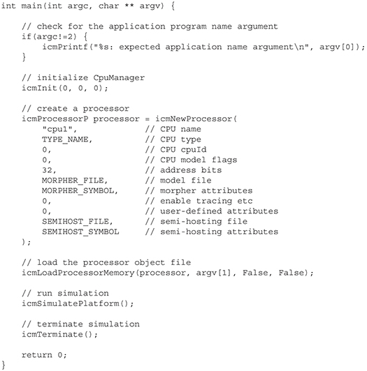
Figure 1. Test platform construct of simple single processor. Source: Imperas
The following paragraphs describe the main operations being performed.
The ICM kernel is initialized by calling icmInit:
icmInit(0, 0, 0);
This function takes three arguments. The first, simAttrs, is a bitmask controlling some aspects of simulation behavior. The two remaining arguments are used when processor debug is required (this is discussed in a later section).
A single instance of a processor is defined by calling icmNewProcessor. Parameters for this routine are:
- name: an instance name to give the instance that must be unique in the design.
- type: a type name for the instance; in this case specified as “or1k” in the makefile.
- cpuId: every processor has an id number, specified by this argument.
- cpuFlags: a bitmask accessed from within the processor model to change its behavior (for example, to turn on debug modes). In normal usage, pass 0.
- addressBits: specifies the default data and instruction bus widths for the model (typically 32, though ICM supports addresses up to 64bit).
- modelFile / modelSymbol: modelFile is the path to the dynamic load library implementing the processor model.
- procAttrs: a bitmask controlling some aspects of processor behavior.
- userAttrs: this argument specifies a list of application-specific attributes for the processor. In this example, the instance has no attributes.
- semiHostFile / semiHostSymbol: these two parameters specify the semihosting library for the processor instance; this is described in the next subsection.
Defining semihosting
The idea of semihosting allows the default behavior of specified functions to be intercepted and overwritten by a semihosting shared object library loaded by the simulator. In this example, it will be used to define the behavior of a program exit. This is a simple example used to terminate the simulation; other semihosting features can be used to provide support for low-level functions that make up functions such as printf using the native host functionality. In this case, a global label, exit, is defined on the last instruction of the assembler test. This will be intercepted by the simulator as defined in the semihosting library, as shown in Figure 2.
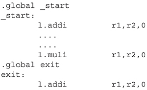
Figure 2. Simulator defined in semihosting library. Source: Imperas
The label can be used in conjunction with a standard semihosting shared object library. This semihosting library terminates simulation immediately after any instruction labeled exit. To use the semihosting library, platform.c includes the semihosting object file name and the name of the semihostAttrs object within that file, as it has been specified by SEMIHOST_FILE and SEMIHOST_SYMBOL, defined in the platform makefile. The SEMIHOST_FILE refers to the name of the .dll file implementing the semihosting. The SEMIHOST_SYMBOL refers to the name of a specific symbol used within the model that defines the semihosting behavior (in this case, impExitAttrs).
This simple example makes no specific mention of any processor memory configuration, other than to say that the processor address bus width is 32 bits. In the absence of any other specific information about memory configuration, OVPsim will create a single fully populated RAM memory attached to both the processor data and instructions busses. In addition, processor address spaces can be explicitly specified to contain separate RAMs and ROMs, with some shared between processors in a multiprocessor system. It is also possible to specify that certain address ranges will be modeled by callback functions in the ICM platform itself, useful for modeling memory-mapped devices. Examples would be UARTs, though a peripheral device can be instantiated as a peripheral instance.
Once a processor instance has been created, an ELF format file can be loaded into the processor memory using:
icmLoadProcessorMemory(processor, argv[1], False, False);
The first parameter is the processor for which to load memory. The second parameter is the application ELF file name. In this example, the application file name is passed as the first argument when the platform is run. The third parameter controls whether the ELF file is loaded using physical addresses (if True) or virtual addresses (if False). This affects only processors implementing virtual memory. The fourth parameter enables debug output showing the location of sections in the loaded ELF file.
There are also memory accessor functions that allow a file loader for any file format to be written in C as part of the platform and used to load program memory. For example, this method would be used to support the loading of hex file formats or S records. Once the processor has been instantiated and an application program loaded, the program can be simulated to completion using: icmSimulatePlatform();
This routine simulates the entire platform using the OVPsim default scheduler that, for multiprocessor platforms, runs each processor for a number of instructions in a time slice before advancing time to run the next time slice.
The routine named icmSimulate is available to simulate a specific processor for a precise number of instructions. This second function is useful in situations when OVPsim is being used as a subsystem of a larger simulation implemented in another environment, such as SystemC. Finally, we use icmTerminate is to clean up simulation data structures and delete all the simulation objects created since the previous icmInit call.
Attaching a debugger
It is possible to attach a debugger using the gdb RSP protocol to a processor in an OVPsim simulation. In order to use debugging, two steps are needed in the platform. First, icmInit must be passed a debug host name and port number as arguments:
icmInit(True, “localhost”, portNum);
Second, the specific processor instance targeted for debug must be given the ICM_ATTR_DEBUG instance attribute:
icmProcessorP processor = icmNewProcessor(
“cpu1”, // CPU name
TYPE_NAME, // CPU type
0, // CPU cpuId
0, // CPU model flags
32, // address bits
MORPHER_FILE, // model file
MORPHER_SYMBOL, // morpher attributes
ICM_ATTR_DEBUG, // CPU attributes
0, // user-defined attributes
SEMIHOST_FILE, // semi-hosting file
SEMIHOST_SYMBOL // semi-hosting attributes
);
When the ICM executable is started, it will wait for a debugger to connect to it on the specified port. If gdb is being used as the debugger, a version of gdb specific to the processor type to be debugged is required.
Multiprocessor support
Any number of processors can be instantiated within an ICM platform, using shared memory resources and callbacks on mapped memory regions to allow communication between them. The following shows the instantiation of two processors and a memory shared between them. Each processor also has a small amount of local memory for stack.
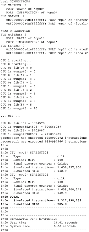
Figure 3. Typical test platform and application output. Source: Imperas
Two processors are instantiated with individual names and unique ID numbers:
// create a processor
icmProcessorP processor0 = icmNewProcessor(
“cpu1”, // CPU name
TYPE_NAME, // CPU type
0, // CPU cpuId
0, // CPU model flags
32, // address bits
MORPHER_FILE, // model file
MORPHER_SYMBOL, // morpher attributes
SIM_ATTRS, // simulation attributes
0, // user-defined attributes
SEMIHOST_FILE, // semi-hosting file
SEMIHOST_SYMBOL // semi-hosting attributes
);
icmProcessorP processor1 = icmNewProcessor(
“cpu2”, // CPU name
TYPE_NAME, // CPU type
1, // CPU cpuId
0, // CPU model flags
32, // address bits
MORPHER_FILE, // model file
MORPHER_SYMBOL, // morpher attributes
SIM_ATTRS, // simulation attributes
0, // user-defined attributes
SEMIHOST_FILE, // semi-hosting file
SEMIHOST_SYMBOL // semi-hosting attributes
);
Two busses are created, one for each processor, and connected to the processors:
// create the processor busses
icmBusP bus1 = icmNewBus(“bus1”, 32);
icmBusP bus2 = icmNewBus(“bus2”, 32);
// connect the processor busses
icmConnectProcessorBusses(processor0, bus1, bus1);
icmConnectProcessorBusses(processor1, bus2, bus2);
This example needs three memories––a local stack memory for each processor and some shared memory, created and connected to the processor busses:
// create memories
icmMemoryP local1 = icmNewMemory(“local1”, ICM_PRIV_RWX, 0x0fffffff);
icmMemoryP local2 = icmNewMemory(“local2”, ICM_PRIV_RWX, 0x0fffffff);
icmMemoryP shared = icmNewMemory(“shared”, ICM_PRIV_RWX, 0xefffffff);
// connect memories
icmConnectMemoryToBus(bus1, “mp1”, shared, 0x00000000);
icmConnectMemoryToBus(bus2, “mp2”, shared, 0x00000000);
icmConnectMemoryToBus(bus1, “mp1”, local1, 0xf0000000);
icmConnectMemoryToBus(bus2, “mp1”, local2, 0xf0000000);
Memory maps for multiprocessor systems can be complex, so it is often useful to be able to show the bus connections using icmPrintBusConnections:
// show the bus connections
icmPrintf(“nbus1 CONNECTIONSn”);
icmPrintBusConnections(bus1);
icmPrintf(“nbus2 CONNECTIONSn”);
icmPrintBusConnections(bus2);
icmPrintf(“n”);
The full memory map of each processor is mapped onto the shared memory object, except for a small section of local memory for each stack. In this example, it means that the load processor memory function need only be used for one processor. The effect of loading a processor’s memory will be to load the shared memory where both processors will execute the same code:
// load the processor object file – because all memory is shared, both
// processors will execute the same application code
icmLoadProcessorMemory(processor0, argv[1], False, False);
The platform is then simulated to completion using the function icmSimulatePlatform.
A set of standard Imperas function intercepts can be enabled by passing ICM_ENABLE_IMPERAS_INTERCEPTS as the first argument of icmInit. In this particular application, the impProcessorId intercepted function within the application is used to access the ID of the processor on which the application is running and to modify the application execution. ICM_VERBOSE is set in this example to enable simulation runtime statistics at the end of simulation:
// initialize CpuManager – require Imperas intercepts because the
// application uses impProcessorId() to get processor id
icmInit(ICM_VERBOSE| ICM_ENABLE_IMPERAS_INTERCEPTS, 0, 0);
When the test platform and application are compiled and simulated, the resulting output is as shown in Figure 3––cpu0 is generating the Fibonacci series with cpu1 reading results from the shared memory.
Peripheral support
A SoC usually includes numerous peripheral devices, such as UARTs and DMA controllers that may use interrupts to communicate with the processors and have master access into the memory space used by the processors. These features are all included and supported within the OVP environment.
Peripheral devices are modeled using a Peripheral Simulation Engine (PSE). Each peripheral is added using a call to icmNewPSE.
icmPseP dmac = icmNewPSE(“dmac”, “dmacModel.pse”, NULL, NULL, NULL);
The new peripheral is defined by five parameters. The first two give the peripheral’s name and the dynamic link library that is loaded by the simulator to define the behavior. The third allows attributes to be passed in order to configure the peripheral’s behavior. For example, these attributes could be used to define a file to write data to, or to define the mode of operation. The final two parameters are used to define a semihosting library to load onto the peripheral to expose host native functions and to allow host peripheral hardware accesses. Examples would include the use of the Ethernet NIC or USB, keyboard.
Summary
Key attributes of OVP––hundreds of MIPS simulation performance, the ease with which a complex multiprocessor/multiperipheral platform can be created, the reusability and interoperability of the OVP models due to the APIs––have been highlighted, although more are available. This open, free solution allows embedded software teams to quickly build and simulate complex multiprocessor/multiperipheral platforms, advancing them toward their goal of higher quality software in a tighter schedule.
The OVP-based platform gives software teams an open standard solution to quickly and inexpensively simulate embedded software on SoC designs. Its ability to handle multicore architectures with a robust set of APIs offers easy modeling of processors, components and platforms.
Imperas
Imperas Buildings
North Weston
Thame
Oxfordshire
OX9 2HA
UK
T: +44 1844 217114
W: www.imperas.com