Object-oriented design for DSP hardware
For years, ASIC and FPGA designers have shared the goal of having totally reusable intellectual property (IP) blocks. This goal has been partially fulfilled, with the introduction of high-level hardware description languages such as VHDL and Verilog, and powerful Register Transfer Level (RTL) synthesis tools in the late 1980s and early 1990s. However, with a few exceptions, most of the IP written for RTL synthesis is substantially modified each time it is used in a new project.
A new design methodology is emerging where the IP blocks and their components are described as classes and templates in C++ and then re-used with the appropriate specializations for a range of different applications. This way, the flexibility of being able to adapt the originally designed block to an application is retained, yet the engineer can still use the original template without any modifications. By adopting this methodology, it is possible to achieve an order of magnitude increase in productivity for the design of digital signal processing (DSP) blocks without major compromises in the quality of results compared with those obtained from hand writing RTL.
Motivation
The original motivation for this exercise came from the design of a digital radio frequency (RF) modulator. The RF modulator’s building blocks include mixers for performing frequency shifting and various low pass and band pass filters to eliminate undesired components of the modulated signal. All of these are implemented as very simple finite impulse response (FIR) filters. The mixers are implemented using digital oscillators and multipliers.
While the architecture of each of the filters and mixers is essentially the same throughout the design, it is not desirable to write a single filter RTL code in VHDL or Verilog and then customize it using generics or parameters. The size, bit-widths, and performance parameters for each permutation are very different. Creating specialized instantiations of a pre-defined filter or mixer as written in RTL would produce an implementation that makes inefficient use of the available hardware resources.
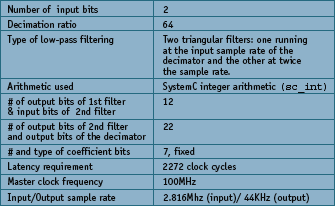
Figure 2. Decimator design requirements
With this in mind, and given the nature of high level synthesis, we decided instead to write a generic description of the filter and the mixer using C++ classes and templates (Note that in this paper we discuss only the filter since it is used in most DSP algorithms. The design procedures for the mixer were the same). This template could then be used to create a specialized micro architecture for each particular application.
The specialization was performed in two steps. First, we wrote the filter (or mixer) description in such a way that its size, bit width, storage type (floating, integer, complex etc.), and coefficients were C++ template parameters. Then we used the architectural exploration capabilities of the Catapult C Synthesis algorithmic synthesis tool from Mentor Graphics to tune hardware resources to the required performance of the filter and the target technology into which the filter was to be implemented.
By following this design approach based on higher-level synthesis, we succeeded in implementing a large proportion of the RF modulator based on a few lines of C++ code.
The basic building block:a programmable FIR template
As mentioned before, RF modulator building blocks contain an FIR filter as a basic building block. A finite impulse response is essentially a DSP engine which, for every output sample, produces the dot product of a state vector times the filter coefficient vector. If N is the length of the filter, the state vector is an array of the current and the previous N-1 inputs presented to the filter. and the coefficient vector is the weight of each of the N inputs at the filter’s output. The filter’s output is described by the following equation:
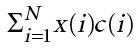
where x is the input vector and c is the coefficient vector. If infinite precision arithmetic were available, the function of the filter – low-pass, high-pass, band-pass, or even complex – would be uniquely determined by the length of the filter and the choice of coefficients. Since all DSP designs have limited precision arithmetic (floating point has a very high dynamic range but it is still finite), other parameters — such as the bitwidths of the filter and the arithmetic in which the filter is implemented — must be described to achieve the desired quantization noise. Consequently, the filter, including its quantization noise, can be uniquely defined with the following parameters:
- Filter length.
- Arithmetic used for the operations (fixed point, integer, floating point complex, etc).
- Precision (number of bits) used for the arithmetic representation of the input, state vector, coefficient vector and output.
- Value of the filter coefficients, which may be programmable.
- Algorithm used to implement the dot product (slight differences in the coding style will produce different implementations. e.g., a shift register versus a circular buffer).
The C++ template can be used to describe the above mentioned parameters. In this template, the length of the filter N is described by the N_TAPS parameter.
template <int N_TAPS,class I_CLASS,class C_CLASS,class
O_CLASS>
class srr_fir_generic {
	public:
		srr_fir_generic ();
		srr_fir_generic (C_CLASS initcoef[N_TAPS]);
		void load(C_CLASS incoef[N_TAPS]);
		O_CLASS exec(I_CLASS input);
	private:
	C_CLASS coef[N_TAPS];
	I_CLASS regs[N_TAPS];
};
The arithmetic used in implementing the filter is specified by the choice of input, coefficient and output classes (I_CLASS, C_CLASS, and O_CLASS). The precision of the arithmetic operations is also specified by the choice of input, coefficient and output classes. In addition, the value of the coefficients can be specified either at compile (synthesis) time by using the following constructor: srr_fir_generic(C_CLASS initcoef [N_TAPS]).
Or the coefficients can be programmed during execution by using the load member function. Finally, the algorithm is coded in such a way that the filters can be implemented as shift registers plus adder trees when synthesized using Catapult C.
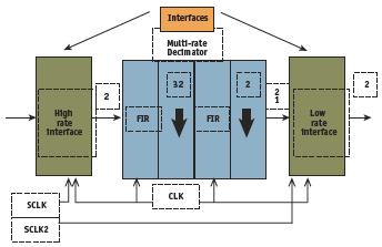
Figure 3. Block diagram of a decimator
To determine if the template could be easily specialized for the multiple functions in an RF modulator, the filter template was used in a variety of different DSP implementations: a decimator; an interpolator using a polyphase filter where the polyphase filter is also a template; and in two different versions of a baseband side band suppression filter — one using two ‘real’ arithmetic filters and the second one using ‘complex’ arithmetic.
Creating the Decimator
The bit widths for the filters and the coefficients were estimated based on the dynamic range of the coefficient values which uniquely determines the bit width of the coefficient vector as well as the gain of each individual filter. The requirements for the decimator are listed in Figure 2 and a schematic of the decimator is shown in Figure 3 .
The latency of the design was estimated based on the ratio of the input sample rate and the master clock. The C++ code to implement such a decimator is very straightforward.
#pragma hls_design top
sc_int <OWORD2> DECIMATOR_MODULE_NAME(sc_int<IWORD1> input[DECIMATION]) {
	static sc_int <CWORD12> coefficients[NP1] = {
		1, 2, 3, 4, 5, 6, 7, 8, 9,10,11,12,13,14,15,16,
		17,18,19,20,21,22,23,24,25,26,27,28,29,30,31,32,33,
		32,31,30,29,28,27,26,25,24,23,22,21,20,19,18,17,
		16,15,14,13,12,11,10, 9, 8, 7, 6, 5, 4, 3, 2, 1
	};

	// Both filters have the same coefficients.
	// The input, coefficient and output bit widths of both filters are different.

	static srr_fir_generic<NP1,sc_int<IWORD1>,sc_int<CWORD12>,sc_int<OWORD1> >
		filter1(coefficients);
	static srr_fir_generic<NP1,sc_int<IWORD2>,sc_int<CWORD12>,sc_int<OWORD2> >
		filter2(coefficients);

	sc_int <OWORD1> result1;
	sc_int <OWORD2> result2;

	const int dec = DECIMATION;
	const int mask = DECIMATION / 2 - 1; // Works only for powers of two careful

	int i;
	int test;

	for (i=0;i<dec;i++) {
		result1 = filter1.exec(input[i]); // This is executed at the input rate.
		test = i & mask;
		if( !test ) { // This is executed at i = 0 and 32.
		// The sample rate for this filter is 1/32 of the input rate
		result2 = filter2.exec(result1);
		}
	}

	// This is executed at the output rate.
	return result2;
} // fourth_order_decimator
There are several interesting aspects to this block of code. First, notice that the decimator returns an output of type sc_int (SystemC integer arithmetic) of width OWORD2 where OWORD2 is defined as 22 as per the decimator specification.
Second, the input of the decimator is an array of DECIMATION words of CWORD12 bits. DECIMATION and CWORD12 are declared as 64 and 7 as per the filter specification. This array will be turned into an input stream (an array in time) during high level synthesis.
Third, two instances of the previously created filter class are declared. The number of taps, as well as the types of the input, coefficient and outputs are declared in a manner consistent with the specification.
Fourth and finally, the body of the decimator is a loop which executes the first filter for each input sample and the second filter every 32 samples as per the specification. This loop defines the outer control loop of the synthesized hardware. At the end of this loop, a single value, the decimated value, is returned.
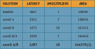
Figure 5. Analysis of the different decimator solutions automatically generated from the same C++ source code
The above described code was synthesized using Catapult C. The filter loops were parallelized to meet the latency requirements of the decimator. Figure 5 shows the results for different micro architectures that were synthesized using an FPGA as the target.
The smallest synthesized hardware with a latency of less than 2272 clock cycles was chosen after a variety of different architectures were explored. The RTL for all of the explored architectures was generated in a matter of hours rather than weeks.Without C synthesis, it would have taken weeks to hand write the RTL for each.
Interpolator Design
Once we had created the FIR filter, the next task was to use the same C++ source code to create an interpolator design. An interpolator using similar low pass FIR filters could have been very easily written with slight modification of the C++. However, to show how easy it is to re-use a template in the object-oriented design paradigm, we wrote an interpolator using a polyphase filter.
Use of polyphase filters for an interpolator design is more efficient computationally than a straightforward implementation of a decimator since computations with the interpolated zeroes are not performed. Essentially, a polyphase filter is built as an array of smaller filters, where the linear dimension of the array is the interpolation factor of the polyphase interpolator: e.g., an interpolator with an interpolation ratio of eight where the implemented low pass FIR has 64 taps is implemented as an array of eight low pass filters, each of them containing 64 taps. To show how the filter class could be re-used, we implemented a polyphase template using an array of(N_PHASES) filters as its storage type.
template <int N_TAPS,int N_PHASES,class I_CLASS,class C_CLASS,class O_CLASS>
class srr_fir_polyphase_fir {
	public:
		srr_fir_polyphase_fir ();
		srr_fir_polyphase_fir (C_CLASS initcoef[N_PHASES * N_TAPS]);
		void load(C_CLASS incoef[N_PHASES * N_TAPS]);
		O_CLASS exec(I_CLASS input);

private:
	int state;
	srr_fir_generic<N_TAPS,I_CLASS,C_CLASS,O_CLASS> filter_array[N_PHASES];
};
From this C++ code, it can be clearly seen that, with exception of the number of phases (N_PHASES), the parameters of a polyphase filter are identical to the parameters of an ordinary FIR filter. Additionally, it can be seen in the private section of the polyphase filter that the storage elements of the polyphase class consists of an array of the finite impulse response filters as defined in the srr_fir_generic template.
When executed the polyphase filter runs one of the FIR phases corresponding to the state of the filter and changes the state of the polyphase filter to the next phase as shown below. Once the polyphase filter class was defined, we wrote a wrapper interpolator function which instantiated two eight-phase polyphase filters which in turn created an interpolation rate of 64. The design of this function is much like the interpolator design.
O_CLASS srr_fir_polyphase_fir<N_TAPS,N_PHASES,I_CLASS,C_CLASS,O_CLASS>::exec(I
_CLASS input) {
	int i;

	O_CLASS result;

	result = filter_array[state++].exec(input);
	if (state == N_PHASES) {
		state = 0;
	}

	return result;
}
// srr_fir_polyphase_fir
Complex Arithmetic Filter
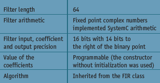
Figure 8. Characteristics of the complex arithmetic filter
So far, we have only described filter-based designs which work with integer or fixed point arithmetic. That might lead one to believe that we are talking of a very restrictive design style. The following example will show that this style is in fact very flexible. One of the architectures considered for the RF modulator that motivated this work was to perform the side band suppression at the baseband using complex arithmetic rather than using a band pass filter at the carrier frequency. Such an architecture requires a filter that has a much lower sample rate than a filter in the carrier frequency band. To demonstrate the power of this methodology, we chose not to implement the complex arithmetic filter as two real arithmetic filters. Instead, we wrote a template which described the basic operations between complex numbers and between ‘real’ and complex numbers, where the ‘real’ numbers are not necessarily floating point numbers, as in traditional programming, but are the storage class defined in the complex template.
By doing this, a complex class composed of two SystemC or integer numbers could be defined. This class implements fixed point complex arithmetic which can be used to implement the desired filter. The following lines of code show a complex arithmetic filter using 16 bit SystemC (sc_fixed) arithmetic:
static srr_fir_generic
<64,sc_fixed<16,2>, srr_complex<sc_fixed<16,2>>,
	                  srr_complex<sc_fixed<16,2>> filter;
This specialization defines the following characteristics for the filter shown in Figure 8. The complex arithmetic filter was synthesized and simulated using both floating point and SystemC arithmetic. Figure 9 shows how one of the side bands of a 500Hz test tone was effectively eliminated.
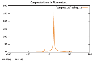
Figure 9. Simulation result of a complex arithmetic filter
Conclusion
We have presented three completely different designs based on a single FIR class. To promote design re-use, various DSP blocks were designed from the same base code. A filter template was first written in C++. This template was then re-used in various digital designs such as a decimator, an interpolator, and the baseband filter of a single sideband modulator.
By re-using the FIR filter design in different contexts, large productivity increases are now possible eliminating days of RTL hand coding for each of the individual designs. The design process for each one of these blocks was performed in a matter of hours rather than weeks when compared with traditional RTL design techniques.
References
- Stroustrup, Bjarne. The C++ programming language. Addisson-Wesley. 2000.
- Elliot, Douglas. Editor. Handbook of Digital Signal Processing Applications. Academic Press. 1987.