Case study: How to apply architectural formal verification to system-level requirements
Introducing one of the latest refinements of formal and showing how ArterisIP and Oski Technology used the strategy on an ARM-based design.
Our reliance on electronic systems is constantly increasing. No sector is immune to their impact. Energy, medicine, manufacturing, communications, finance, travel and entertainment – all are controlled by complex electronic devices. The demands they place on device capabilities create design complexities that open up risks in terms of safety and security.
The more complex the design, the greater the chance that some bugs may go undetected. These bugs can have catastrophic consequences, including crashing an airplane or exposing sensitive systems to cyber-criminals. Identifying and fixing these bugs in software can itself be difficult but can often be addressed with a software update. Hardware design bugs, such as those that leave systems susceptible to cache attacks, are much more daunting to identify and fix.
What’s needed is more system-level verification. We have traditionally relied on SoC simulations of the RTL and in-circuit emulation (ICE) to verify system-level requirements. These approaches model and test the entire chip at a relatively low level of abstraction. The coverage of corner-case scenarios when using these methods is, however, low. That raises the possibility of subtle system-level bugs surviving verification.
Design houses recognize that letting these bugs pass undetected is no longer an option, and are turning to formal verification to strengthen the design process. Formal uses mathematical techniques to explore all possible design behaviors. It can provide complete coverage, equivalent to that achieved by simulating all possible scenarios. The goal is that no bugs are left behind.
But formal model checking suffers from the exponential challenge associated with PSPACE-complete problems. It cannot deliver the solution for system-level verification challenges alone. It must be coupled with a sound methodology. One such methodology adopts an ‘architectural formal verification’ approach to verify system-level requirements such as the absence of deadlock and cache coherence.
This case study describes the key components of that methodology and how ArterisIP and Oski Technology worked together to deploy it.
So what do we mean by ‘architectural formal verification’?
Architectural formal verification
Architectural formal verification leverages the exhaustive analysis capability generally inherent in formal verification. It explores all corner cases and uses highly abstract architectural models to overcome complexity barriers, enabling deep analysis of design behavior. This combination delivers effective system-level requirements verification that targets areas not well covered by traditional verification methods.
An additional benefit is that architectural formal verification can be deployed early in a project because it does not rely upon the availability of RTL models. Architectural bugs can therefore be detected and fixed before they propagate throughout an implemented design. Contrast that with full-chip simulation or emulation techniques that find architectural bugs later in the verification cycle. Such delays can result in many RTL design changes, since fixing these types of bugs often has a ripple effect that spans out to many blocks. You want to avoid that type of code churn because it can lead to significant setbacks in verification maturity and, in turn, delay time-to-market.
An architectural formal verification methodology has three main steps:
- Block-level architectural modeling
- System-level requirements verification
- Block level implementation verification.
Let’s consider each in more detail.
Block-level architectural modeling
An architecture model (AM) is created for each block that contributes to the system-level requirement being verified. Hierarchical designs necessitate that system-level requirements must be decomposed and distributed among block-level components. This forms a contract by which blocks must deliver specific functionality that contribute to satisfying system-level goals.
The block AMs include only a small slice of the blocks’ functionality. Each slice models the contract for an individual system-level requirement. A collection of block AMs forms a set of abstract models from which all other block-level design details are excluded.
Take the verification of the absence of system-level deadlocks as an example.
The block AMs include only the functionality related to forward progress. They model behavior such as the passing of control through Start/Done messages, wait states encountered due to limited availability of resources, and flow control at interfaces through backpressure or credit-based protocols.
The verification of system-level cache coherence is similar because the block AMs need only include the logic that tracks cache-line states.
The block AMs are coded with a combination of SystemVerilog Assertion (SVA) properties and SystemVerilog RTL code. A key aspect of the AMs is that the output response of the blocks is controlled using SVA properties that are set as assumptions. These assumptions are used during the third stage, block-level implementation verification, to verify the implementation.
The block AMs also include non-deterministic models for the latency through the blocks. This allows a variable range of timing options to be explored and the discovery of bugs related to corner-case combinations of block latencies. A side benefit is that block-level timing specifications can be developed by discovering the limitations of acceptable timing parameters at the system-level.
System-level requirements verification
The system-level architectural model is built from a collection of block level AMs. The formal sign-off methodology is used to prove that system-level requirements hold for this architectural model.
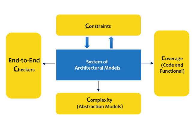
The formal sign-off process can be broken down into ‘The Four Cs’. (Figure 1)
- End-to-end Checkers
- Constraints
- Dealing with Complexity
- Formal Coverage

Figure 1. The formal verification sign-off process includes (from clockwise right) Coverage, Complexity, Checkers and Constraints (ArterisIP/Oski Technology)
End-to-end Checkers.
These differ from typical assertion-based checkers. They model the end-to-end behavior of the block-under-test, and predict what the output should be based on the input, much like a scoreboard.
Think of a forward progress checker. It might be coded to check that when some activity is observed at the input, a corresponding output should arrive within a finite time, accounting obviously for acceptable blocking conditions.
The end-to-end checking logic is typically coded using specialized abstraction techniques to make them suitable for formal use. This is important. It means that the logic does not add too much complexity to the state space of the model being formally verified.
Constraints.
Formal verification explores all possible input stimuli by default. It is therefore important to filter out the illegal input space with constraints and eliminate false failures of the checkers. Care must be taken to verify that there are no over-constraints that could mask real failures and cause bugs in the design to be missed.
Constraints can be verified through formal methods such as assume-guarantee and by running constraints as assertions in the system-level simulation environment.
Dealing with Complexity.
Formal verification may hit complexity barriers even for system-level architectural design, especially when dealing with end-to-end checkers. This sets the requirement for the next piece of the methodology, abstraction models. These reduce the state space or latency of the design so that formal verification can explore beyond its default threshold.
Reset abstraction offers a good example. It is a commonly used technique that allows formal analysis to reset the design to deep sequential states. Design behavior can be explored around those deep states that would otherwise be unreachable if formal started at the default reset state.
Formal Coverage
Formal coverage is a key component of the sign-off methodology. It measures controllability: How many of the design states have been explored by the input stimuli? It also has a unique ability to report observability coverage: How many of design states are checked by end-to-end checkers? This makes formal coverage a strong metric for measuring progress and closing verification holes.
Block-level implementation verification
The third and final step in the architectural formal verification flow checks that the RTL implementation of the blocks will guarantee the system-level contract that was assumed for the AMs. The modeling logic of an AM and the SVA code assume properties that govern the output behavior are turned into a checker for the RTL code of the block by now asserting those properties.
This step is an equivalency check between the AMs and the RTL model, undertaken one block at a time. It closes the loop on the architectural verification process to ensure that the implementation has not introduced bugs that would cause the design to fail to meet its architectural requirements. The problem becomes tractable since it is decomposed to a sequence of block-level verification tasks. A failure observed in this step due to a mismatch between the two models would detect a bug in the architectural specification from which the AM was derived, a bug in the AM itself or a bug in the RTL model.
ArterisIP and cache coherent system-level verification
Implementation of architectural formal verification
Having defined the flow’s main components, let’s take a look at how ArterisIP and Oski Technology implemented this formal methodology for cache-coherent interconnect system-level verification.
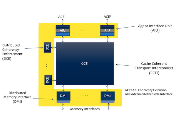
A block diagram of the system is shown in Figure 2. The system supports the interface protocol for the Arm Advanced eXtensible Interface (AXI) with AXI Coherency Extensions (ACE).

Figure 2. The cache coherent interconnect system-level verification methodology (ArterisIP/Oski Technology)
The system has four main components.
- The Agent Interface Unit (AIU) enables CPU clusters with lower level caches to connect with an ACE interface to the cache-coherent interconnect system and share a common memory.
- The Distributed Coherency Enforcement (DCE) block maintains the system directory and is responsible for the snoop-filtering functions.
- The Distributed Memory Interface (DMI) allows compute clusters to access physically separated memories as one logically shared address space.
- The Cache Coherent Transport Interconnect (CCTI) is the interconnect fabric that provides routing, switching and flow control of memory-access transactions.
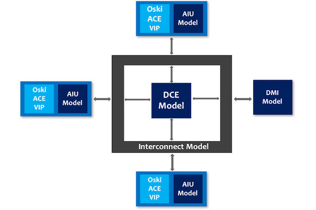
The formal verification environment was built with AMs for each component.
The system also used Oski ACE verification IP components to check that it conformed to the ACE protocol and to constrain formal analysis to explore only legal ACE stimuli (Figure 3).
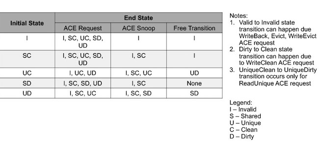
AMs tracked transactions on a per-cache line basis.
The state of each cache line was modeled, as illustrated in Table 1.
A number of system-level properties were verified on this collection of AMs. Cache coherence properties are defined as: “When one agent has a cache line in unique state, all other agents will have it in invalid state” and “No two agents will have a cache line in dirty state.” The data integrity property verifies that dirty data will not be dropped. Deadlock avoidance properties ensure that all transactions will complete in a finite time if no known blocking conditions exist.
Abstraction techniques were used during formal analysis to help overcome complexity limitations. The reset abstraction was used for cache line states allowing the cache line states in all agents to take any legal value at reset. The reset state of the snoop filter also was allowed to be non-deterministic, but constrained to legal values based on the selected cache line state in the various agents.
Another abstraction limited the number of active cache lines being tested at any one time. However, the addresses of active cache lines were defined with symbolic constants. Effectively, the entire address space was covered.
Results of architectural formal verification
The results were dramatic. The architectural formal verification process uncovered design issues during each of the three major steps of the flow.
The first step revealed that the simple creation of abstract block-level models uncovered some architectural specification issues before formal verification was run on the models. That is typical of any process that takes a design description and captures it in executable form, such as documenting design intent with assertions. For example, this led to the discovery that a new type of snoop message to model evictions was required.
The second step of testing the system of AMs unearthed numerous protocol-level bugs related to cache coherence, data integrity and the ACE protocol. Examples of bugs found in each area, respectively, were:
- Returning shared permissions to an ACE master holding a cache line in the unique state;
- Loss of dirty data when WriteBack from an ACE master was closely followed by a read request from another master; and
- Returning dirty data to an ACE master holding cache line data in the unique state.
Additional RTL bugs were found by formal verification during the third step of testing AMs against RTL models. These bugs had gone undetected in RTL simulation.
Conclusion
The verification of system-level requirements is a critical challenge. The problem is not well addressed by traditional methods and a subtle bug that slips through to production can have disastrous consequences.
Architectural formal verification is the next big leap in the evolution of formal applications. It can be performed at an early phase of design development, before RTL implementation begins, to improve the quality of the architectural design as well as the specification. Once the RTL code is ready, RTL models can be tested to confirm they conform to the contract required of them at the system-level, which improves the quality of the design implementation.
About the authors
Chirag Gandhi has more than 12 years of semiconductor industry experience and currently serves as senior design verification manager at ArterisIP, based in San Jose, California. He has held positions at Netlogic Microsystems (acquired by Broadcom), Oracle and AMD, where he worked on the verification and validation of assorted designs at the IP and SOC level. Gandhi has a Master of Science degree in Electrical and Computer Engineering from Georgia Institute of Technology.
Roger Sabbagh is vice president of applications engineering at Oski Technology. He has more than 25 years of experience in the semiconductor and electronic design automation (EDA) industries. Most recently, he was senior principal engineer at Huawei Technologies, where he led the formal verification team. Sabbagh holds a Bachelor of Electrical Engineering degree from Carleton University, Ottawa, Canada.


