The ‘What’, ‘When’, and ‘How Much’ of functional coverage
Up to 80% of the overall design cycle time can today be spent on verification. Constrained-random testing (CRT) was developed in response to greatly reduce the amount of code needed to create a verification environment. However, CRT-based methodologies that do not include functional coverage are analogous to shooting blind [1].
Functional coverage provides essential feedback for knowing what was tested, the device configuration used and, perhaps most important, what still has not been tested. It is thus indispensable to answering the fundamental verification question, ‘Are we done yet?’
We must remember that it is a feedback mechanism only — however, that feedback does allow verification to be focused on in completely tested areas.
Coverage-driven verification
Coverage-driven verification (CDV) is a natural complement to constrained-random testing (CRT). It is important to understand the different types of coverage that can be used in verification and ‘total coverage analysis’.
Functional coverage
Functional coverage is one facet of a total coverage analysis methodology that includes assertions and code coverage. Each helps determine, ‘Are we done yet?’ It focuses on the actual functionality of the design and is closely tied to its specification. Some facets of the functionality will be ‘must haves’; others will be ‘nice to haves’. A properly executed functional coverage plan will identify these and can be useful in gating a design for tapeout. In this case, 100% of the ‘must haves’ will be exercised, but perhaps only 85% of the ‘nice to haves’.
Code coverage
Code coverage answers a different question, ‘Has all the code been exercised?’ It says nothing of the correctness of that code nor can it address unimplemented functionality. It does provide a measure of the completeness of testing. Any unexercised code either has not been stimulated during verification or is redundant. Functional and code coverage are complementary since both help reveal holes in the verification.
Assertion coverage
Ideally, designers embed assertions in RTL code to specify its function and monitor for out-of-bounds operations. For example, an arbiter may be specified to only accept three simultaneous transactions. Assertions can be coded to flag an error or warning if this limit is exceeded.
Functional coverage goals
Coverage goals depend on the type of coverage and the figures may be different in each case. It may be possible to achieve 100% code coverage but less than 100% functional coverage. This is because code coverage cannot tell us anything about unimplemented functionality; by definition, functional coverage can.
There is no definitive way of setting coverage goals. The target may be 80%, 90% or 100%, but what do these figures actually represent? The real goal is confidence that the functionality is correct. It is usually a combination of:
- Number of test runs
- Bug discovery rate
- DUT stability
- Marketing (i.e. Schedule!)
It is our experience that this last factor often determines when a chip is ready to ship. With well-defined coverage goals, at least it is possible to assess the risk of taping-out early.
The three functional coverage questions
The coverage plan is central in the verification plan in a CDV approach and leads to the three fundamental questions of functional coverage: ‘What?’ ‘When?’ and ‘How much?’ Without careful consideration, you will get data overload. If you dread reading your coverage reports, you have a problem.
What to cover?
The first consideration in creating a functional coverage plan is determining what should be covered. There are several different kinds of object for which functional coverage is appropriate. A useful source of what to cover is, obviously, the design specification. Others can include:
- System specification
- Interface specification
- Standard protocol specifications
- On-chip protocol specifications
- Design specification
- Design engineers (for embedded items)
For the functional items themselves, these include any ‘interesting’ events or scenarios, basic functionality, state machines, and protocols (both embedded and external).
A consideration of where to sample can help determine what to sample. Boundaries between different levels of abstraction are appropriate places to look for data items to sample (e.g., applying a frame of data to a system that breaks the frame into packets to send to one part of an SoC — here we have the frame boundary and the packet-level abstraction). The packets themselves may be decomposed into lower-level objects.
Our test environment may be composed of transaction-level models (TLMs) that convert one level of abstraction to another. TLMs often include ‘analysis ports’ [3] that observe appropriate transactions as they flow through the model. Such ports provide a natural interface to the coverage model.
If there are any corner cases in a design, these should also be covered. Examples include FIFOs of buffer occupancy levels becoming full/empty, etc.
In a CRT-based environment, the configuration of the device-under-test (DUT) itself may be randomly generated. The configuration will also need to be covered to ensure that all legal modes of operation have been used.
A consideration in what to sample is to ensure the sampled items are interesting (e.g., a datacoms packet may have a cyclic redundancy check (CRC). The CRC’s value does not reveal any interesting information since it is a computed number but its validity is relevant).
When to sample?
Appropriately timing when to sample coverage data is key to avoiding data overload. Engineers who are new to a CDV methodology often over-sample, typically using the system clock as the event to trigger coverage. It is important to use the correct granularity not only to minimize the data collected but also to maximize its information content. If a state machine is being covered, it is more interesting to sample on state changes rather than every clock edge.
When deciding what to sample, we looked at where to sample. This also helps determine when to sample. Abstraction level boundaries use much coarser events than the clock (e.g., a single event when a whole frame of data is applied to a device, whereas many events are emitted each time a packet is transferred to a transactor). TLM analysis ports may already include the appropriate events for sampling.
As well as dynamic, run-time coverage, if we are randomizing device configurations, we need to sample coverage after randomization. Such device configurations may use a configuration object which is generated before simulation starts but which is then transacted into the DUT to set the mode of operation. Another consideration is to ensure that data is valid when it is sampled and there are no race conditions present.
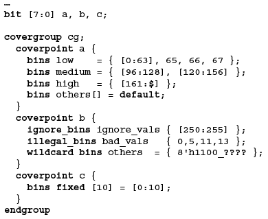
Figure 1. Using the coverpoint bins construct
How much to sample?
The key to using coverage successfully is to minimize the data collected but to maximize its information content.
Functionally equivalent samples. In many cases, individual data values have no functional significance. For example, the payload bytes of a packet may have no functional impact on the operation of the DUT beyond a couple of specific values. Values that are significant can have their own groups and all the rest can be lumped together into bins. This greatly reduces the data to process. The example in Figure 1 (p20) shows how the coverpoint bins construct can be used. There are also options to ignore certain values and to specify illegal values. It is better to have explicit monitors for any illegal states or values though.
Cross coverage. Another source of excess data is blindly sampling items that are not interesting. For example, if a router is being verified, one of the coverage items may be the different type of packet (e.g., small, large, headless, tail-less etc.). If coverage is only performed on packet type, then a large volume of data is collected. Of greater interest is to see what type of packet comes out of which output ports. This example of cross-coverage usually reveals more about the operation of the DUT than the individual items.
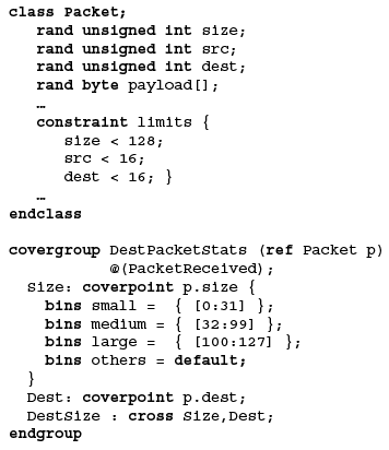
Figure 3. Packet sizes grouped into three categories and a cross made with the destination port
In Figure 2, packet sizes have been grouped into three categories and a cross made with the destination port. Grouping the packet sizes into three bins reduces the cross product from 128*16 to a more manageable 3*16.
For cross coverage, the contribution of each item and cross to the overall coverage goal should be considered. By default, all coverpoints and crosses have the same weight. This can lead to an unrealistically high overall coverage grade. The weight of the individual items should be set to zero.
Conditional sampling. An important consideration in coverage sampling is to ensure that data is relevant (e.g., not sampling DUT outputs during the reset or configuration phase). SystemVerilog’a coverage model allows very fine-grained control of the conditional enabling of data capture as Figure 3 shows.
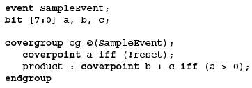
Figure 3. Fine-grained control of the conditional enabling of data capture with SystemVerilog
Transition coverage. This allows sequences of changes of values to be sampled. Figure 4 (p21) shows a state machine, but transition coverage can be used for any sequence of operations — e.g., verifying that every configuration register has had a read-write-read test performed.
Architecting coverage in SystemVerilog
In a CD-CRT methodology, coverage is central, not an afterthought. It is crucial to incorporate it in a flexible, reusable and controllable manner. CRT is class-centric so it makes sense to take advantage of this when implementing coverage.
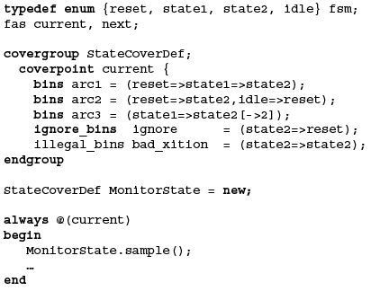
Figure 4. State machine
Class-based
Covergroups, as effectively user-defined types, can be embedded in classes. This provides encapsulation of the coverage model. A consideration for dynamic data objects is whether we really want each object to have its own coverage group. As we are interested in statistics of the objects themselves, it may be more appropriate to use a single cover group to collect the information and have the dynamic objects call the sample() method of the single group when appropriate.
A more flexible approach used in the Mentor Graphics Advanced Verification Methodology embeds a covergroup in a derivative of an avm_subscriber. This offers a flexible user interface and a means to attach to an analysis port. Figure 5 shows the skeleton of this approach.
Control issues
The embedded covergroup in Figure 5 is shown without a sampling event. The only way to trigger coverage is to use the group’s sample() method. This is extremely flexible since the user controls exactly when coverage is sampled. Whether a sampling event is used or not, a group’s sample() can be used to trigger coverage at any arbitrary point in time.
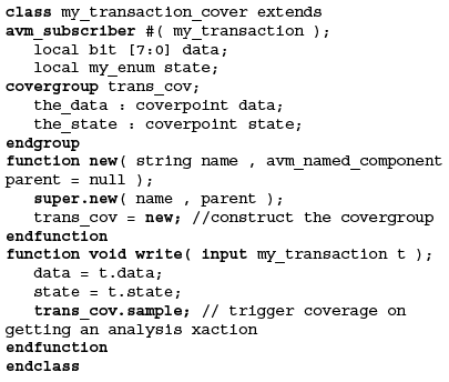
Figure 1. Embedding a covergroup in a derivative of an avm_subscriber with the Mentor Graphics Advanced Verification Methodology
Summary
SystemVerilog has powerful coverage features that allow implementation of a Coverage-Driven Constrained-Random test environment. We have demonstrated techniques to determine the ‘What?’, ‘When?’ and ‘How much?’ of coverage sampling using SystemVerilog so that the fundamental question of verification, ‘Are we done yet?’, can be answered with confidence.
References
- “The Shotgun Approach to Verification – Don’t Shoot Blind-folded” by Chuck Mangan and Paul Marriott. Presented at DVCon2003, San Jose, CA, February 24-26, 2003.
- IEEE P1800 SystemVerilog Language Reference Manual.
- “Implementing TLM in SystemVerilog” by Adam Rose and Tom Fitzpatrick. Presented at DATE2006, Munich, Germany, March 7-11, 2006.
- Questa Simulator Reference Manual 6.2a, Mentor Graphics Inc.
XtremeEDA Corporation
555 Legget Dr.,
Suite 140,
Tower B,
Kanata, ON
K2K 2X3
Canada
T: +1 613-254-9685 or 1-800-586-0280
F: +1 613-254-8571
www.xtreme-eda.com